 Boats For Sale:


Not another Mustang restoration thread. |
Post Reply 
|
Page <1 4445464748 54> |
| Author | |
TRBenj 
Grand Poobah 

Joined: June-29-2005 Location: NWCT Status: Offline Points: 21109 |
 Post Options Post Options
") Thanks(0) Thanks(0)
 Quote Reply Quote Reply
 Posted: January-23-2019 at 11:57am Posted: January-23-2019 at 11:57am |
I have seen plenty of boats with waterline cracking that didn�t have floor separation issues, and several boats with floor separation issues that showed no signs of waterline cracking. I�m inclined to think that there is less of a direct link associated with those 2 things than has been suggested on this site. Correlation does not equal causation. |
|
 |
|
|
JoeinNY
Grand Poobah

Joined: October-19-2005 Location: United States Status: Offline Points: 5693 |
Post Options
Thanks(0)
Quote Reply
Posted: January-23-2019 at 12:45pm |
Stress concentrations on flexible surfaces bad - how you avoid/cure them can be many ways - including removing the flex of the flexible surface. The horizontal stress cracking I have on the passenger side of my ski nautique was certainly at the wettest area of the floor/foam and had disbond of the floor at that location. Was there an impact or flaw that caused the cracking, Disbonded the floor, let in water and caused the rot or was there rot/wet foam that froze, expanded, and pulled the floor away from the hull causing the stress cracking. If I had to guess I would say the latter scenario was more likely as there was no cracking of the glass anywhere just separation, but I can't rule out a bad floor to hull bond from the factory. Relatively rigid well bonded foam in the floor changes things quite a bit... |
|
|
|
|
john b
Grand Poobah
Joined: July-06-2011 Location: lake Sweeny Status: Offline Points: 3236 |
Post Options
Thanks(0)
Quote Reply
Posted: January-23-2019 at 9:08pm |
|
The material to make gaskets for the risers came today. Time to start getting the engine ready for paint. I polished a few more parts and I like the way they look.. I can't bring myself to rattle can them. They add a little bling to what would otherwise be a dipped in house paint original look.
 
|
|
|
1970 Mustang "Theseus' paradox"
If everyone else is doing it, you're too late! |
|
|
|
|
KENO
Grand Poobah
Joined: June-06-2004 Location: United States Status: Offline Points: 10650 |
Post Options
Thanks(0)
Quote Reply
Posted: January-23-2019 at 10:24pm |
|
John
My keen x ray vision seems to think there's a Pertronix module cleverly hiding under the distributor cap.............or maybe it's the red and black wires telling me that Could you put an orange oil filter on the engine to go along with the Pertronix module so Pete will be clutching his heart and mumbling something about "the big one"  
|
|
|
|
|
john b
Grand Poobah
Joined: July-06-2011 Location: lake Sweeny Status: Offline Points: 3236 |
Post Options
Thanks(0)
Quote Reply
Posted: January-23-2019 at 11:29pm |
|
Ha, Good eye. Bless Pete's heart but it has original parts sans paint. It's going to be a family ski boat used by many, not a garage queen. My kids will end up with it. If they don't like it they can get a can of spray paint and paint those parts or sell it..
I went through the distributor rebuild some pages and possibly some years back. It took a lot of restraint not to order a DUI for it and be done. This isn't my first Pertronix ignition. I have had them in several boats I have owned and have put hundreds of hours on them. Tune never changes unless it fails, and if it does, so what? I can use the Alumitoon or put the breaker plate with points back in until Prime brings me a new one the next day. This Mustang isn't perfect. It has some scratches and a few chips. I'm sure it will get more. |
|
|
1970 Mustang "Theseus' paradox"
If everyone else is doing it, you're too late! |
|
|
|
|
8122pbrainard
Grand Poobah

Joined: September-14-2006 Location: Three Lakes Wi. Status: Offline Points: 41040 |
Post Options
Thanks(0)
Quote Reply
Posted: January-23-2019 at 11:35pm |
  
|
|
|
|
|
67 ski nat
Platinum Member 
Joined: July-19-2018 Location: Santa rosa Status: Offline Points: 1181 |
Post Options
Thanks(0)
Quote Reply
Posted: January-24-2019 at 10:54am |
|
Very nice. Show off the brass copper fittings. I polished mine and then clear coated with engine enamel.
|
|
|
|
|
TRBenj
Grand Poobah
Joined: June-29-2005 Location: NWCT Status: Offline Points: 21109 |
Post Options
Thanks(0)
Quote Reply
Posted: January-24-2019 at 11:31am |
|
Eh, the chrome engine bits look great, as do the polished hull hardware... paint the rest.
|
|
|
|
|
Hollywood
Moderator Group

Joined: February-04-2004 Location: Twin Lakes, WI Status: Online Points: 13510 |
Post Options
Thanks(0)
Quote Reply
Posted: January-24-2019 at 11:56am |
|
Eh
|
|
|
|
|
Riley
Grand Poobah

Joined: January-19-2004 Location: Portland, ME Status: Offline Points: 7946 |
Post Options
Thanks(1)
Quote Reply
Posted: January-24-2019 at 12:13pm |
|
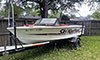
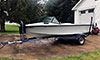
This is what ours looked like 10 years ago. I bet they don't look like that now...

|
|
|
|
|
john b
Grand Poobah
Joined: July-06-2011 Location: lake Sweeny Status: Offline Points: 3236 |
Post Options
Thanks(0)
Quote Reply
Posted: January-29-2019 at 2:00pm |
|
I have searched for a thread detailing how to locate the correct engine position on the new stringers. In my mind this is a critical task since the adjustment only allows for the rear elevation and lateral movement of the engine. This must have been discussed before. Can someone point me to a thread or help me with this please?
BTW Petes old engine alignment 101 vid is well done. 75K views is impressive. Love that young version of Pete! |
|
|
1970 Mustang "Theseus' paradox"
If everyone else is doing it, you're too late! |
|
|
|
|
storm34
Grand Poobah

Joined: November-03-2008 Location: Dexter Iowa Status: Offline Points: 4492 |
Post Options
Thanks(1)
Quote Reply
Posted: January-29-2019 at 3:05pm |
|
John, I could be wrong but I think placement of the front mounts is dependent on shaft length once the distance between strut and prop are set rather than a set distance from the factory.
I've been down this road with the promo when we swapped the 318 for the 340 and installed a new ARE shaft. New shaft was intentionally shorter but we still ended up moving everything back 3" in order to get an optimal measurement between the strut and prop. I'd say it's better to test fit what you have to ensure everything works together. My thought would be to install the shaft (with coupler and prop) then drop in the engine and slide forward or backwards based on distance hanging off the strut. |
|
|
|
|
TRBenj
Grand Poobah
Joined: June-29-2005 Location: NWCT Status: Offline Points: 21109 |
Post Options
Thanks(1)
Quote Reply
Posted: January-29-2019 at 3:13pm |
|
Less shaft length and more shaft angle dependent- along with weight balance. Going back a little vs original placement can free up some space at the front of the motorbox/pylon and hasn’t been proven to upset the hull handling (should make a marginal improvement in attitude). I wouldn’t go the opposite direction.
|
|
|
|
|
Riley
Grand Poobah
Joined: January-19-2004 Location: Portland, ME Status: Offline Points: 7946 |
Post Options
Thanks(1)
Quote Reply
Posted: January-29-2019 at 4:32pm |
|
You can shim higher, but not lower. Make sure your stringers/cradle aren't too tall. Do a test fit after your framing is glassed in to make sure you're within the tolerances to align. Install your strut, shaft log and shaft/coupling and make sure it'll line up with the new stringers/cradle.
|
|
|
|
|
john b
Grand Poobah
Joined: July-06-2011 Location: lake Sweeny Status: Offline Points: 3236 |
Post Options
Thanks(0)
Quote Reply
Posted: January-29-2019 at 7:16pm |
|
OK, I think I've got this.
1. Get everything glassed down. 2. Install strut with new cutlass bearings. 3. Install shaft and do a rough engine alignment with the shaft in the center of the log. 4. Bolt front engine mounts down. 5. Align engine. I"m ready to cut and shape the new stringers from the Coosa I laminated. I still plan to make them 1/2" shorter to accomodate a Coosa floor and retain the original elevation. I think it will work out well not only for the floor but for the engine elevation since I plan on using 2" X 2" X 1/2" aluminum angle drilled and tapped on top of the stringers to bolt the engine to. Talk me out of it if you think this is a really bad idea. I hoped to do the cutting and shaping outside to limint the hazardous dust in my garage but the forcast for Chicago is cold for the next few days. |
|
|
1970 Mustang "Theseus' paradox"
If everyone else is doing it, you're too late! |
|
|
|
|
TRBenj
Grand Poobah
Joined: June-29-2005 Location: NWCT Status: Offline Points: 21109 |
Post Options
Thanks(1)
Quote Reply
Posted: January-29-2019 at 7:25pm |
|
#2 will obviously require a test fit of the shaft to make sure you are aligning the strut to the log.
4 and 5 are swapped. 2” x 2” x 1/2” angle? Now you’ve lost me. |
|
|
|
|
Hollywood
Moderator Group
Joined: February-04-2004 Location: Twin Lakes, WI Status: Online Points: 13510 |
Post Options
Thanks(1)
Quote Reply
Posted: January-29-2019 at 7:51pm |
|
|
|
|
|
john b
Grand Poobah
Joined: July-06-2011 Location: lake Sweeny Status: Offline Points: 3236 |
Post Options
Thanks(0)
Quote Reply
Posted: January-29-2019 at 7:51pm |
|
#2 will obviously require a test fit of the shaft to make sure you are aligning the strut to the log.
I understand the need to align the log to the strut prior to engine alignment. 4 and 5 are swapped. I am confused by this. My thought is that the front mount must be secured to the stringer prior to alignment, but the lateral alignment adjustment should be left loose to slide the engine for alignment, and the rear mounts should be loose to slide the wedges for elevation adjustment. If the front mounts are not secured to the stringer there would be no lateral stability. As you know the H/M mounts allow for several inches of lateral adjustment. Is my thinking seriously flawed? 2” x 2” x 1/2” angle? Now you’ve lost me. I plan on through bolting 2' X 2" X 1/2" thick aluminum angle stock to the stringer since Coosa does not hold lag bolts well. This will raise the height of the stringer 1/2" in the engine mounting area which is about 3' on each stringer. |
|
|
1970 Mustang "Theseus' paradox"
If everyone else is doing it, you're too late! |
|
|
|
|
john b
Grand Poobah
Joined: July-06-2011 Location: lake Sweeny Status: Offline Points: 3236 |
Post Options
Thanks(0)
Quote Reply
Posted: January-29-2019 at 7:57pm |
Correct Hollywood. That is exactly what I am thinking of. It's not a cradle, just aluminum angle oon top of the stringers through bolted longetudinally. I also want to have my fabricator make aluminum wedges to replace the original wood ones for the rear mounts. I think the H/M mounts are a bit different than others but have similar functionality. |
|
|
1970 Mustang "Theseus' paradox"
If everyone else is doing it, you're too late! |
|
|
|
|
KENO
Grand Poobah
Joined: June-06-2004 Location: United States Status: Offline Points: 10650 |
Post Options
Thanks(1)
Quote Reply
Posted: January-29-2019 at 8:09pm |
|
I don't think I've ever seen 2 x 2 x 1/2.
I've seen 3/8 thick but not 1/2 How about a picture of this stuff? |
|
|
|
|
john b
Grand Poobah
Joined: July-06-2011 Location: lake Sweeny Status: Offline Points: 3236 |
Post Options
Thanks(0)
Quote Reply
Posted: January-29-2019 at 8:22pm |
The 1/4" stock is 2" X 2" X 1/4". I would like it as thick as possible for the engine mounting bolt purchase. 3/8 may be sufficient. Click and ship right to your door. 1/4" aluminum angle stock |
|
|
1970 Mustang "Theseus' paradox"
If everyone else is doing it, you're too late! |
|
|
|
|
TRBenj
Grand Poobah
Joined: June-29-2005 Location: NWCT Status: Offline Points: 21109 |
Post Options
Thanks(1)
Quote Reply
Posted: January-29-2019 at 8:48pm |
|
I share kens skepticism on that size angle being available. Even if it were, it would leave you with only 1.5” inside height. Center the through bolt in that 1.5” and you’re within 3/4” of the top of the stringer (then subtract bolt radius). Awfully close to the top. I’d go a lot taller (at least 4” but I’d aim for 6”).
I also don’t love the idea of drilling and tapping the angles for the mount bolts. Why not scallop the stringer and through bolt the mounts/wedges similar to the way it was done in the 80’s? If you’re trying to determine engine placement, I would do a gross alignment check first (engine floats until you’re happy with its location), then lock it down, then proceed with the fine alignment using your adjustment features. |
|
|
|
|
KENO
Grand Poobah
Joined: June-06-2004 Location: United States Status: Offline Points: 10650 |
Post Options
Thanks(1)
Quote Reply
Posted: January-29-2019 at 9:01pm |
What he said, especially the part about using mounting bolts and nuts and scallops 4 x 2 x 1/4 is pretty readily available. 6 x 2 maybe. |
|
|
|
|
john b
Grand Poobah
Joined: July-06-2011 Location: lake Sweeny Status: Offline Points: 3236 |
Post Options
Thanks(0)
Quote Reply
Posted: January-29-2019 at 9:04pm |
I could go with 3 X 2 X 1/4. What is the concern about drilling and tapping the mounting holes? I am not familiar with the 80s mounting method. I believe having a channel about 3" long will provide plenty of room for multiple through bolts to secure them. 1/4" aluminum angle stock |
|
|
1970 Mustang "Theseus' paradox"
If everyone else is doing it, you're too late! |
|
|
|
|
8122pbrainard
Grand Poobah
Joined: September-14-2006 Location: Three Lakes Wi. Status: Offline Points: 41040 |
Post Options
Thanks(1)
Quote Reply
Posted: January-29-2019 at 9:05pm |
|
John,
I agree with Tim's concern. If you do move forward with your current plan, I do recommend going with the 3/8 plus using fine thread bolts into the angle. This will give you more threads in the relatively soft aluminum. His other concern of getting the through bolting low enough in the stringer can be overcome with using a 2x3 angle with the 3 leg down. |
|
|
|
|
john b
Grand Poobah
Joined: July-06-2011 Location: lake Sweeny Status: Offline Points: 3236 |
Post Options
Thanks(0)
Quote Reply
Posted: January-29-2019 at 9:20pm |
Brain fade. Yes, I agree. I am typing 1/4 when I mean 1/2. The 3/8 is available and my fabricator can get or make 1/2" Don't know why I was saying 1/4 and referring to bringing the height up 1/2. |
|
|
1970 Mustang "Theseus' paradox"
If everyone else is doing it, you're too late! |
|
|
|
|
SNobsessed
Grand Poobah
Joined: October-21-2007 Location: IA Status: Offline Points: 7102 |
Post Options
Thanks(1)
Quote Reply
Posted: January-29-2019 at 10:32pm |
|
You could locally weld some 1/4 imaterial n the area where it will be tapped, giving you 1/2 total thread length. Then scallop out room for the 'nut'.
|
|
|
“Beer is proof that God loves us and wants us to be happy.”
Ben Franklin |
|
|
|
|
john b
Grand Poobah
Joined: July-06-2011 Location: lake Sweeny Status: Offline Points: 3236 |
Post Options
Thanks(0)
Quote Reply
Posted: January-30-2019 at 1:03pm |
|
Thanks for the suggestions. I like the method of scalloping the stringers and using nuts to secure the engine mounting bolts. I will order the 3/8 3 X 2 angle and plan on doing it that way unless someone has other input.
It's nice having an engeering team with decades of experience willing to help a guy out. This thing just might turn out ok. You guys are truly the best! |
|
|
1970 Mustang "Theseus' paradox"
If everyone else is doing it, you're too late! |
|
|
|
|
TRBenj
Grand Poobah
Joined: June-29-2005 Location: NWCT Status: Offline Points: 21109 |
Post Options
Thanks(1)
Quote Reply
Posted: January-30-2019 at 1:14pm |
|
1/4” is fine and I’d go taller than 3”.
If you want to be able to remove the engine without pulling the floor, you’ll want to think about how you will access those nuts on the underside of the scallops. Some creativity will be required on the floor to main stringer joints in the area of the engine. Reverse mounting the angles (vertical leg on outside of stringer, access to nuts from the inside) has crossed my mind, but not all mount styles will play nicely with that. It would allow a clean floor to stringer joint though. (I’d add a lip 1/2” down on the outside for the floor panel to catch. |
|
|
|
|
john b
Grand Poobah
Joined: July-06-2011 Location: lake Sweeny Status: Offline Points: 3236 |
Post Options
Thanks(0)
Quote Reply
Posted: January-31-2019 at 4:29am |
|
A little progress tonight. I shaped/fitted one primary stringer and got the second one cut out and ready for shaping./fitting. I am considering making 2 small passages between the stringers and the floor to allow water to drain to the bilge. The originals had 2 holes each side for that in the area where the exhaust hose lays. Without foam some water may collect there. Is this a good idea? I am also considering not installing the original floor pan. It has some damage around the pylon where the PO enlarged the hole slightly for an extended boom support. The trim ring almost covers it but not quite. There is also significant wear where the front of the motor cover rests.. I have more than enough storm gray Nautilex left over from another project to do the floor. If I don't like it the Nautilex it should work as an underlayment for the pan.
Work resumes tomorrow. . |
|
|
1970 Mustang "Theseus' paradox"
If everyone else is doing it, you're too late! |
|
|
|
|
Post Reply
|
Page <1 4445464748 54> |
 Tweet
Tweet
|
| Forum Jump | Forum Permissions You cannot post new topics in this forum You cannot reply to topics in this forum You cannot delete your posts in this forum You cannot edit your posts in this forum You cannot create polls in this forum You cannot vote in polls in this forum |


 Topic Options
 Hollywood wrote: