 Boats For Sale:


No spark! |
Post Reply 
|
Page 12> |
| Author | |||
wakemeup 
Senior Member 

Joined: July-11-2008 Location: Culver City, CA Status: Offline Points: 113 |
 Post Options Post Options
") Thanks(0) Thanks(0)
 Quote Reply Quote Reply
 Topic: No spark! Topic: No spark!Posted: August-11-2008 at 7:56pm |
||
|
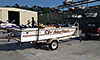
I have an 88 Ski Nautique, 351 W, RR. The boat was not running when I bought it. It did not have a spark with the original points ignition, so I bought a whole new Mallory distributor, new plug wires, and ballast resistor. I have a new coil on order.
I am getting fuel to the carb, but I am not getting a spark out of the coil. I have done the following: 1. Hooked a voltage meter to both positive and negative side of coil and get 11 volts with key in the on position (not cranking). When I crank it the volts on the positive side of the coil drops to 8. 2. Hooked bug light up to negative side of coil, cranked engine and the light stays on steadily. 3. I checked for spark by attaching a jumper wire to the the #1 plug wire and held it close to the thermostat housing, nothing. I also hooked up a timing light. Neither method produced a spark. 3. The new distributor has three wires coming from it, a green, brown and red. I hooked the green to the negative side of the coil, the brown to a ground on the carb linkage and the red to the ballast resistor. I'm guessing I have something wired wrong. Will I still get a spark if I have the distributor not installed at TDC with cylinder number one. What about if I have the timing order off on my plug wires? I've double checked these but I could still be off. May need another set of eyes. I have gone back three years looking at every thread on this subject and am stumped. Any help would be greatly appreciated. George |
|||
|
Wakemeup
1988 Ski Nautique 1999 Air Nautique |
|||
 |
|||
|
TRBenj
Grand Poobah 

Joined: June-29-2005 Location: NWCT Status: Offline Points: 21124 |
Post Options
Thanks(0)
Quote Reply
Posted: August-11-2008 at 9:23pm |
||
Based on your description, I think youre right.
Yes- even with both of those snafus, you'll still get spark at both the coil and plugs- though the engine probably wont run. Im not familiar with the Mallory wiring, but my guess is that you have it mixed up. I assume the new dist came with instructions? My guess is that the wires should be hooked up to ign+ (coil +), gnd, and trigger (coil -), but I dont know which color lead is which. FYI, it wasnt clear by your description how you were measuring the voltage. The positive (red) lead of the meter should be on the point in question (+ side of coil, etc) and the negative (black) lead should be on a good ground- like an engine bolt. Measuring from the + side of the coil to the - side doesnt tell you much. The - side is the trigger and not a ground, so the voltage at that point will vary from 0 to 12V. I would think that the test light should be flashing when hooked to it (while cranking). If you check the instructions and it turns out that you have it wired correctly, try bypassing the ballast resistor as a test until the new one comes in. Ive had a bad resistor cause a no-spark condition. If you are getting a constant 12V to the + side of the coil, its wired correctly, and still no spark, then the only things left are the coil or ign module in the dist. |
|||
|
|||
|
wakemeup
Senior Member
Joined: July-11-2008 Location: Culver City, CA Status: Offline Points: 113 |
Post Options
Thanks(0)
Quote Reply
Posted: August-11-2008 at 11:00pm |
||
I bought the distributor from SKIDIM and wired it the way they said on their website and also confirmed it with Vince, that is: Green wire to negative side of coil, red wire directly to positive side of ballast resistor and brown to ground. I'll check with Mallory on this in tomorrow. Oh, and the distributor did not come with any instructions As far as checking for voltage at the coil, I hooked up the black lead of the volt meter to ground and then the red to the positive side of the coil and got 12 volts and then touched the red to the negative side and got 12 volts. I did not check the volts across the negative and positive sides of the the coil. I actually have a new ballast resistor installed, its the coil that I am waiting for. I also did this on the ballast resistor if it helps anyone. With key in on position: Place red lead from volt meter to one side of ballast resistor and black to ground: I get 12 volts. I do the same thing on the other side and get 12 volts. Doing the same thing with the engine cranking I get 9 volts on either side. Does this sound right? Thanks in advance! |
|||
|
Wakemeup
1988 Ski Nautique 1999 Air Nautique |
|||
|
|||
|
Booty
Groupie 

Joined: July-30-2007 Location: United States Status: Offline Points: 46 |
Post Options
Thanks(0)
Quote Reply
Posted: August-12-2008 at 1:11am |
||
|
Was the distributor installed correctly rotor at #1 wire location at TDC? Just asking. Sometimes you think its TDC and can be on exhaust stroke. Or 180 Out.

|
|||
|
Booty
82,2001 82,2001 |
|||
|
|||
|
wakemeup
Senior Member
Joined: July-11-2008 Location: Culver City, CA Status: Offline Points: 113 |
Post Options
Thanks(0)
Quote Reply
Posted: August-12-2008 at 1:26am |
||
As far as I know, it was at TDC on the compression stroke. It blew my thumb off of number one cylinder and I then rotated the motor forward to 10 degrees BTDC (the mark on the damper) I then lined up the rotor with the number one cylinder plug wire. Anyway, according to TRBenj (see his last reply) even if I screwed this up it would not prevent me from getting a spark. Thanks for your input. |
|||
|
Wakemeup
1988 Ski Nautique 1999 Air Nautique |
|||
|
|||
|
eric lavine
Grand Poobah
Joined: August-13-2006 Location: United States Status: Offline Points: 13413 |
Post Options
Thanks(0)
Quote Reply
Posted: August-12-2008 at 9:34am |
||
|
the ballast resister is used to drop your voltage you should see 12 volts on one side and 8-9 volts on the output side of the resister. I ran into this last week with a mallory and he had the wrong coil installed so match up your part numbers and make sure you are using a mallory breakerless coil, with the coil resisted correctly you should see aproximately 8 or so volts at the coil on the positive side with your gruond on the engine block, not the coil
the only thing that throws me is when your cranking, i would think you should see 12 volts at one end of the resister all the time unless you have it wired incorrectly |
|||
|
"the things you own will start to own you"
|
|||
|
|||
|
79nautique
Grand Poobah

Joined: January-27-2004 Location: United States Status: Offline Points: 7872 |
Post Options
Thanks(0)
Quote Reply
Posted: August-12-2008 at 12:25pm |
||
|
your ground choice is weak, your wiring is wrong and the timing is advanced.
Both wires go to the coil and ground to the block, you should have set the timing mark at 0 before installing the dist not 10 now you will have atleast 15-20 degrees of advance dialed in. Also if you are readying 12v on both sides of the coil then it's bad or you didn't measure it corretly. green (-) term red (+) term on coil, black attach to a block ground. |
|||
|
|||
|
wakemeup
Senior Member
Joined: July-11-2008 Location: Culver City, CA Status: Offline Points: 113 |
Post Options
Thanks(0)
Quote Reply
Posted: August-12-2008 at 1:56pm |
||
I'm using the old coil until I get the new one from Summit that was recommended by Mallory for this distributor. I don't know why its taking so long. The one I have looks like an old coil. I didn't know there were breakerless coils. Sounds like that could be the problem or part of it. I'll also check the wiring on the ballast resistor. Thanks for your help. |
|||
|
Wakemeup
1988 Ski Nautique 1999 Air Nautique |
|||
|
|||
|
wakemeup
Senior Member
Joined: July-11-2008 Location: Culver City, CA Status: Offline Points: 113 |
Post Options
Thanks(0)
Quote Reply
Posted: August-12-2008 at 2:25pm |
||
I was waiting for someone to comment on my choice for the ground. The problem is that the connector Mallory gives you is so damn small its hard to find a small enough bolt on the block. Anyway, I'll take it off the carb linkage and make it work. I'll try running both wires to the coil like you said after I get the new coil. I am getting about 11.5 volts on both sides of the coil. It must be bad As far as setting the initial timing. Is this correct? Please comment if this isn't right or if you have a better way. 1. Find TDC at number one cylinder. I use the thumb method. 2. Rotate the engine forward to 0 degrees on the damper. 3. Install distributor with rotor lined up with number one spark plug wire on the cap. 4. Start engine and set timing to 10 degrees BTDC with timing light. I don't think I can get to this stuff today (work) or tonight (going to Dodger game) but hopefully Wednesday afternoon/evening. Thanks for your help. |
|||
|
Wakemeup
1988 Ski Nautique 1999 Air Nautique |
|||
|
|||
|
79nautique
Grand Poobah
Joined: January-27-2004 Location: United States Status: Offline Points: 7872 |
Post Options
Thanks(0)
Quote Reply
Posted: August-12-2008 at 2:44pm |
||
|
wire the coil right with the coil you currently have, you have it back feed that's why it isn't firing.
don't get excited about the marks lining up bump it until your thumb blows off or just starts to and then line up the rotor you be close enough to get it started. |
|||
|
|||
|
wakemeup
Senior Member
Joined: July-11-2008 Location: Culver City, CA Status: Offline Points: 113 |
Post Options
Thanks(0)
Quote Reply
Posted: August-18-2008 at 1:42am |
||
|
Still no spark. I do not get a spark from the main, center coil wire that goes to the center of the distributor.
This is what I have done since my last post. 1. Installed new coil (this is coil that Summit recommended for this distributor) 2. Attached red wire from distributor to positive terminal of coil along with purple wire from power source. 3. Attached green wire to negative side of coil along with the grey tach wire. 4. Attached brown wire to coil clamp hold down bolt on intake manifold for ground. I stripped the wire back and then tightened bolt. 5. I get 11 volts on both the negative and positive side of coil. Can you wire the ballast resistor backwards? Thanks in advance for your expertise. 


(post updated by moderator for image alignment purposes only) |
|||
|
Wakemeup
1988 Ski Nautique 1999 Air Nautique |
|||
|
|||
|
79nautique
Grand Poobah
Joined: January-27-2004 Location: United States Status: Offline Points: 7872 |
Post Options
Thanks(0)
Quote Reply
Posted: August-18-2008 at 11:24am |
||
|
still got a piss poor ground, ground it to the block not the intake not the head to the block, there should be an empty tapped hole to use on the drivers side front of the block to use. Get a bolts for it, a waster and lock washer and add a ring terminal to the brown wire, clean the block of paint before attaching wire.
|
|||
|
|||
|
MdFooter
Senior Member

Joined: January-30-2008 Location: Lakeland, FL Status: Offline Points: 100 |
Post Options
Thanks(0)
Quote Reply
Posted: August-19-2008 at 1:39am |
||
|
George,
I extended my brown grounding wire for this distributor all the way to the block ground where the battery cable hooks up. 79 is right, you need a better ground. The resistor works the same both ways. From what I can see in the picture, it appears that you have the red wire from the distributor attached to the pos(+) terminal on the coil which is reduced voltage from the resistor. If you're using the Mallory YLM554CV, this red wire needs to be attached to a good 12VDC, i.e. the 'high' side of the resistor or the ignition circuit. (Per their wiring diagram). You should be measuring batt. voltage on the red wire of the resistor and this needs to feed the distributor for it to work properly. As far as coils, I finally had success with the Mallory 29705. In the case of 12VDC on both side of the coil, I would recommend disconecting the gray tach lead from the neg(-) side of the coil and also disconnecting the electric choke for now at least until you have spark. Then re-connect one at a time. Let us know how it goes! |
|||
|
|||
|
79nautique
Grand Poobah
Joined: January-27-2004 Location: United States Status: Offline Points: 7872 |
Post Options
Thanks(0)
Quote Reply
Posted: August-19-2008 at 11:42am |
||
|
[QUOTE=MdFooter] From what I can see in the picture, it appears that you have the red wire from the distributor attached to the pos(+) terminal on the coil which is reduced voltage from the resistor. If you're using the Mallory YLM554CV, this red wire needs to be attached to a good 12VDC, i.e. the 'high' side of the resistor or the ignition circuit. (Per their wiring diagram). You should be measuring batt. voltage on the red wire of the resistor and this needs to feed the distributor for it to work properly.
QUOTE] THIS IS NOT RIGHT AND YOU ARE USING THE WRONG DIAGRAM. the wiring is fine just needs a better ground connection. Ran mine that way for years never had a problem and worked right off the bat. |
|||
|
|||
|
MdFooter
Senior Member
Joined: January-30-2008 Location: Lakeland, FL Status: Offline Points: 100 |
Post Options
Thanks(0)
Quote Reply
Posted: August-20-2008 at 1:30am |
||
|
Chris,
I am not second-guessing your knowledge about ignition systems, but I believe there is an important difference here. You have the optical trigger and I have the magentic. Maybe the optical works fine with 9-10VDC? I don't know. In your own post to 77, you quoted the Mallory installation instructions that said: The 3 wires coming from the UNILITE� Distributor must be connected using the distributor wire harness furnished (see Figures 1 and 2). RED WIRE: If you use loom resistance wire, connect to the coil (+) terminal. (Fig 1) If you use a ballast resistor, connect to 12 volt side of ballast resistor. (Fig 2) These are the exact same instructions for the magnetic and are what I tried to explain above. George, Do you have the YLU or YLM? Another question is how do you know if you have loom resistance wire? Should you assume that you don't? All I know for sure is that once I ran a seperate new plain wire from the ignition switch to the resistor post, and then tapped off 12VDC for both the distributor circuit and the new alternator exciter circuit, everything worked. (fig 2) I yield to your position on coils, I changed too many things at once to definitively say which coils will or won't work. But George at least get yourself a good ground and try putting the red wire back to the 12VDC side of the resistor. (Fig 2) Again I would recommend pulling off the tach wire and the 12V feed to the electric choke, eliminates two variables at least. I believe the steady bug light on the negative side of the coil is something to look into like TRB said. 
|
|||
|
|||
|
79nautique
Grand Poobah
Joined: January-27-2004 Location: United States Status: Offline Points: 7872 |
Post Options
Thanks(0)
Quote Reply
Posted: August-20-2008 at 11:34am |
||
|
|||
|
|||
|
MdFooter
Senior Member
Joined: January-30-2008 Location: Lakeland, FL Status: Offline Points: 100 |
Post Options
Thanks(0)
Quote Reply
Posted: August-20-2008 at 1:47pm |
||
|
You're right, the wiring issue is that the harness is 23 years old and severely corroded. Absent a complete new wiring harness for the boat (which I'd love to find) I'm replacing the most crucial wires.
Not re-engineering, just replacing what was already there. |
|||
|
|||
|
79nautique
Grand Poobah
Joined: January-27-2004 Location: United States Status: Offline Points: 7872 |
Post Options
Thanks(0)
Quote Reply
Posted: August-20-2008 at 1:53pm |
||
|
you can buy the one for the motor from skidim the other two try the Regionel dealers maybe.
cleaning the contacts at the connection of the harness usually will take care of any issue. |
|||
|
|||
|
wakemeup
Senior Member
Joined: July-11-2008 Location: Culver City, CA Status: Offline Points: 113 |
Post Options
Thanks(0)
Quote Reply
Posted: August-22-2008 at 4:45am |
||
Thanks for your input and the diagrams! I didn't forget about this thread but this 60 hour work week is killing me. Anyway, I do have the YLM554CV. Today I put my ground were Chris suggested on the block. I soldered the connection and removed all the paint. Unfortunantly, I ran into starter problems which is a whole other thread that I should have started. I will be getting a new starter tomorrow and I will try all of the things you guys have recommended, including removing the tach and choke wires. I will let you know what works, if anything. George |
|||
|
Wakemeup
1988 Ski Nautique 1999 Air Nautique |
|||
|
|||
|
79nautique
Grand Poobah
Joined: January-27-2004 Location: United States Status: Offline Points: 7872 |
Post Options
Thanks(0)
Quote Reply
Posted: August-22-2008 at 10:25am |
||
|
I believe you are never going to get a spark with the current Distributor has I noticed a key issue YLM-554-CV notice the CV on the end of that part number pretty sure that is a standard rotation unit DV is rev. And I do not recall when CC switched to STD and the 1.23:1 tranny so If your motor is a reverse rotation engine then this is a problem and I how you did not damage the gears on the cam or distributor if it is the wrong one.
|
|||
|
|||
|
wakemeup
Senior Member
Joined: July-11-2008 Location: Culver City, CA Status: Offline Points: 113 |
Post Options
Thanks(0)
Quote Reply
Posted: August-22-2008 at 2:49pm |
||
Good catch and you had me scared sh@%tless until I did some research. It turns out that for the YLU series you are correct, but for the YLM they do not distinguish between RH and LH with a CV or DV. (I don't know about their new numbering system) There're all CV and then they put the appropriate gear on. Prior to me installing this distributor I made sure that the teeth on the old Prestolite were going the same way as the new Mallory. Anyway, the starter should be her in the next few hours and I'll see if I can at least get a spark. Thanks for your insight. Also SKIDIM sent me the diagram below (and no, my 12 year old daughter did not draw it) for how they recommend wiring everything which is the same as MDFOOTER's diagram, however Mallory told me to wire it like you said. We'll see this afternoon what works. 
|
|||
|
Wakemeup
1988 Ski Nautique 1999 Air Nautique |
|||
|
|||
|
79nautique
Grand Poobah
Joined: January-27-2004 Location: United States Status: Offline Points: 7872 |
Post Options
Thanks(0)
Quote Reply
Posted: August-22-2008 at 3:08pm |
||
|
if you are going to wire it this way, per diagram, then you better get an extra module to throw in the boat and keep with for when you burn up the module.
Mallory uses a completely new number system now and the CV DV made a difference, you need to go to mallory's site not Jegs or summit but regardless they do not use the YLU-XXX-XX system anymore. just double check the rotation of the rotor the way it is installed currently and make sure it spins CCW and why you are at it make sure the firing order is correct for the rotation of the rotor as well. |
|||
|
|||
|
79nautique
Grand Poobah
Joined: January-27-2004 Location: United States Status: Offline Points: 7872 |
Post Options
Thanks(0)
Quote Reply
Posted: August-22-2008 at 3:36pm |
||
|
|||
|
wakemeup
Senior Member
Joined: July-11-2008 Location: Culver City, CA Status: Offline Points: 113 |
Post Options
Thanks(0)
Quote Reply
Posted: August-22-2008 at 3:49pm |
||
Good stuff! I've always wondered why a distributor for a LH and RH always turns counterclockwise. It defies logic when you think in terms that the distributor should turn in the same direction as the crank. It doesn't because of the direction of the helix on the gear. It still has to sink in with me but I'm a lot closer, I'd like to see a picture of the two gears together at work(cam and distributor) for a RH and LH application. |
|||
|
Wakemeup
1988 Ski Nautique 1999 Air Nautique |
|||
|
|||
|
79nautique
Grand Poobah
Joined: January-27-2004 Location: United States Status: Offline Points: 7872 |
Post Options
Thanks(0)
Quote Reply
Posted: August-22-2008 at 3:53pm |
||
|
just make sure yours spins CCW if it doesn't then, well might have to replace it or the gears but sounds like you should be ok since you did a pretty smart move by comparing the two before installing, but double check both, rotation and firing order, kinda need to check the basics again to make sure you didn't over look something on accident.
|
|||
|
|||
|
wakemeup
Senior Member
Joined: July-11-2008 Location: Culver City, CA Status: Offline Points: 113 |
Post Options
Thanks(0)
Quote Reply
Posted: August-23-2008 at 2:37am |
||
|
Alright I'm starting to lose it. I installed a new (rebuilt starter) and still do not get a spark. I'm starting to wonder if I'm checking for a spark correctly. This is how I checked it: 1. Hold the end of the wire from the center of the coil next to the thermostat housing and I get nothing. The end I am holding next to the thermostat housing is the end that goes to the center of the distributor.
2. Held the number one spark plug wire next to the thermostat housing and get nothing. What kind of spark should I see? Anyway as far as the wiring I have tried both methods; that is attached the red wire from the distributor to the positive side of the ballast resistor and also tried attaching it to the positive side of the coil. I have also disconnected the tach wire and the choke wire(red wire). With the ignition on and engine not cranking I get 12 volts on both sides of the coil regardless of where I place the red wire from the distributor(ballast resistor or coil) When I crank the engine the volts drop to about 8.5 on both sides of the coil regardless I where I place the red wire from the distributor. When I place a bug light on the negative side of the coil and crank the engine it dims but stays lit steadily. Also the rotor does turn counterclockwise. The coil I purchased is part number 29716 from Mallory. "Universal 12 Volt HIgh-Output Coil". It was recommended for this distributor by Summit. Anyone want to jump in on this one! Thanks |
|||
|
Wakemeup
1988 Ski Nautique 1999 Air Nautique |
|||
|
|||
|
wakemeup
Senior Member
Joined: July-11-2008 Location: Culver City, CA Status: Offline Points: 113 |
Post Options
Thanks(0)
Quote Reply
Posted: August-23-2008 at 3:04pm |
||
|
Something doesn't seem right. On the positive side of my ballast resistor I get 12 volts with ignition on and not cranking. When I crank it drops to 9 volts, so I took the positive wire(red) off the resistor and hooked up the volt meter directly to it. I got 12 volts but when I cranked the motor it drops to 9 again. Why would my voltage drop like this? This can't be right.
|
|||
|
Wakemeup
1988 Ski Nautique 1999 Air Nautique |
|||
|
|||
|
MdFooter
Senior Member
Joined: January-30-2008 Location: Lakeland, FL Status: Offline Points: 100 |
Post Options
Thanks(0)
Quote Reply
Posted: August-23-2008 at 6:52pm |
||
|
George,
My son's football schedule has taken away our skiing time for now so I did some analysis in my driveway to try and find some answers here. 1) The YLM dist works fine with 9VDC or 12VDC. Verified this by switching the red distributor wire from the 'high' side of the resistor to the 'low' side. Engine ran fine both ways. 79 was right again and he feels very strongly about running only 10VDC to the distributor. Bottom line is that your voltage to the distributor is fine either way. 2) With the ignition circuit on, and the engine NOT running, the voltage to the (+)post of the coil is about 7VDC. The voltage on the (-) post of the coil is 1VDC. With the engine running, the (+) comes up to about 9.5 and the (-) about 5. Also when I applied the bug light to the (-) the motor quit due to the coil being grounded out. That I believe is the problem. The negative post should not be reading 11V like you said. The green wire out of the distributor should not have anything else attached to it save for the tach lead at the post. If you are reading 11V on the green wire something is wrong with the distributor. As far as your spark testing method, it may be kind of hard to see a spark jump out from all the way inside the wire boot, so I just stick the spark plug in the boot and hold the spark plug tip against some metal on the block. Even a short crank will show you spark that way. |
|||
|
|||
|
wakemeup
Senior Member
Joined: July-11-2008 Location: Culver City, CA Status: Offline Points: 113 |
Post Options
Thanks(0)
Quote Reply
Posted: August-24-2008 at 5:53am |
||
Md, Thanks for your time and research. I've got to give the boat troubleshooting a break for a while, we're taking the motor home out for the next 6 days. Anyway, when I get back I'll look into why that ground is reading 11 volts. Maybe I should put the old Prestolite in just to see if I get a spark. I'll let you know how it goes. Thanks again. George |
|||
|
Wakemeup
1988 Ski Nautique 1999 Air Nautique |
|||
|
|||
|
79nautique
Grand Poobah
Joined: January-27-2004 Location: United States Status: Offline Points: 7872 |
Post Options
Thanks(0)
Quote Reply
Posted: August-24-2008 at 11:13pm |
||
|
well if the spark isn't strong enough to clear the boot then you really don't have a strong enough spark to fire the engine, the spark should jump a good 1/2" or so easy.
also did you ever change the ground brown wire from the distributor to the good ground source of the Block? because if you haven't then quit d*cking around untill you do ok. |
|||
|
|||
|
Post Reply
|
Page 12> |
 Tweet
Tweet
|
| Forum Jump | Forum Permissions You cannot post new topics in this forum You cannot reply to topics in this forum You cannot delete your posts in this forum You cannot edit your posts in this forum You cannot create polls in this forum You cannot vote in polls in this forum |


 Topic Options
 wakemeup wrote: