 Boats For Sale:


Stringer Replacement 86 Silver Nautique. |
Post Reply 
|
Page <1234> |
| Author | |
andrewmarani 
Senior Member 
Joined: May-31-2005 Location: Baltimore, MD Status: Offline Points: 214 |
 Post Options Post Options
") Thanks(0) Thanks(0)
 Quote Reply Quote Reply
 Posted: October-03-2023 at 1:00pm Posted: October-03-2023 at 1:00pm |
|
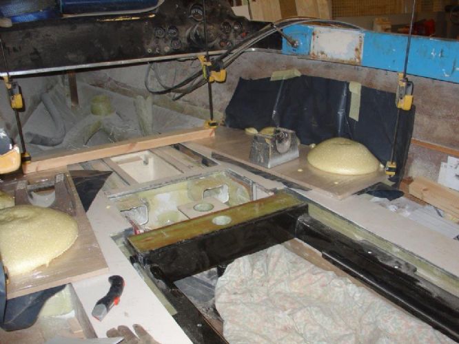
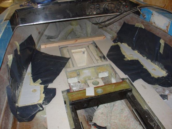
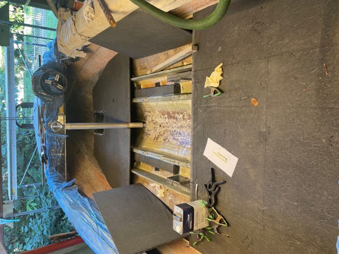
so, smooth ply with plastic wrap on them and holes in the ply to pour the foam through. I see the weights and clamps to hold the boards down as the foam expands.
I see the yellow foam at the holes and where it puffed out around the edges. Is the white material a flooring that you held down with the plywood? Like the giant air ducts!
|
|
|
Builder
|
|
 |
|
|
uk1979
Platinum Member 
Joined: June-13-2007 Location: United Kingdom Status: Offline Points: 1410 |
Post Options
Thanks(0)
Quote Reply
Posted: October-03-2023 at 12:37pm |
|
More pictures I'm a bit rusty on posting..
  |
|
|
Lets have a go
56 Starflite 77 SN 78 SN 80 BFN |
|
|
|
|
uk1979
Platinum Member
Joined: June-13-2007 Location: United Kingdom Status: Offline Points: 1410 |
Post Options
Thanks(0)
Quote Reply
Posted: October-03-2023 at 12:32pm |
|
Did something similar but wrapped the foam in DPC plastic sheeting, left plenty above, just lift out the foam section.. fold over and get the DPC firm as you can with tape, then go over it with a heat gun to shrink it tight.
I put a plastic packer on top before foaming to give room to fold over, I think its not needed if you heat gun it, I used pallet stretch wrap over my blanking boards with holes in. Have fun and do what work for you ..  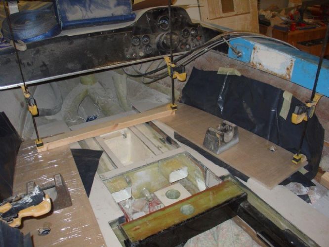 |
|
|
Lets have a go
56 Starflite 77 SN 78 SN 80 BFN |
|
|
|
|
andrewmarani
Senior Member
Joined: May-31-2005 Location: Baltimore, MD Status: Offline Points: 214 |
Post Options
Thanks(0)
Quote Reply
Posted: October-03-2023 at 9:59am |
|
Well, i'm long past that point. Coosa floor is basically cut and fitted for the entire boat. Plus my abilities to fiberglass in a flat floor over the foam are probably not up to that level of finish, not without a lot of fairing compound and sanding.
|
|
|
Builder
|
|
|
|
|
TRBenj
Grand Poobah 

Joined: June-29-2005 Location: NWCT Status: Offline Points: 21109 |
Post Options
Thanks(0)
Quote Reply
Posted: October-03-2023 at 9:44am |
|
Why put a Coosa floor over foam cavities? Seems a waste. Just glass over the foam like the factory did. Save the coosa for the spans over the bilge.
|
|
|
|
|
andrewmarani
Senior Member
Joined: May-31-2005 Location: Baltimore, MD Status: Offline Points: 214 |
Post Options
Thanks(0)
Quote Reply
Posted: October-03-2023 at 9:34am |
|
Getting close to foam time so I've been reviewing posts on foaming the hull. I could start foaming from secondary stringer to the side of the boat now in most of the boat. I will be using 2 lbs foam from US Composites.
The idea of drilling holes in the Coosa floor and pouring in foam makes me nervous because I cannot tell if i've foamed the entire cavity. Plus I'm putting a bunch of holes in the new Coosa floor that I have to patch. However, it does seem the easiest solution. One way to insure a full cavity would be to fill cavities before the floor goes down and then shave the foam flush with the top of the stringers. I would then use a large notch troll to spread thickened epoxy on the foam and set the floor on top with some sand bags to weight it down and let the epoxy set up. I expect it would be hard to shave down the foam flat and it would take a lot of epoxy to bond the floor to the foam. Another way would go insure a full cavity is to pour the foam into the cavity, stretch some plastic tight over the stringers and set the floor panel on top with some weight on the floor panel. Let the foam expand to the underside of the floor panel/plastic and harden. Take up the floor and peel off the plastic. If I do it neatly I should have a smooth flat foam finish, then epoxy the floor down as as noted above. Has anyone done anything other than the holes through the floor method? Any thoughts on the other two methods I've outlined above? Can someone who's foamed a 1986 Nautique or similar boat give me an idea of the quantity they used? I will calculate it out but that's going to be a rough number considering the curving shape and differing depths involved. Thanks
|
|
|
Builder
|
|
|
|
|
andrewmarani
Senior Member
Joined: May-31-2005 Location: Baltimore, MD Status: Offline Points: 214 |
Post Options
Thanks(0)
Quote Reply
Posted: September-21-2023 at 4:26pm |
|
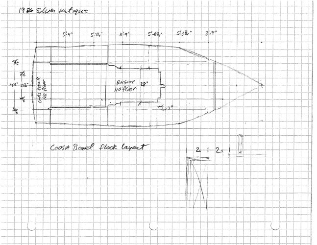
This is the Coosa Board cut plan. Per this plan you need two ¼” x 4x8 sheets and four ½” x 4x8 sheets. All the long skinny pieces are for the stringers. The stringer pieces on the ¼” board are for the secondary stringers and they are 6” wide x 8’ or 6’ or 4’. The stringer pieces on the ½” boards are the main stringers and they are 8” wide x 8’ or 5’ or 2’-6”. The rest is pretty obvious, the only funky thing is I made the floor piece up under the bow by laminating two ¼” pieces together, otherwise you would need to buy another sheet to finish up. If you are careful in your layout and cutting there will be plenty of small scraps left to make up the extra pieces next to the exhaust hoses, the little shelf on either side of the engine and the various other odds and ends, like the two roughly 11” x 14” pieces on either side of the gas tank. Dotted lines on the one piece are the cut out for the removable panel behind the engine. I would wait to cut that out till the final fitting of the floor pieces after everything under the floor is installed. Side note: since the Coosa board is only a 1/2" thick, I added a 1" tall x 1/2" thick piece of scrap to the Coosa board that makes up the non-stringer side of the exhaust hose space. I put it on the outboard side, the side closer to the secondary stringer. So the top of that piece is now 1" wide to give more landing space for the removable panel. You can see it in one of my other pictures.
|
|
|
Builder
|
|
|
|
|
andrewmarani
Senior Member
Joined: May-31-2005 Location: Baltimore, MD Status: Offline Points: 214 |
Post Options
Thanks(0)
Quote Reply
Posted: September-21-2023 at 3:34pm |
|
This is the floor layout plan using 4x8 sheets of Coosa or any 4x8 sheet material. You can ignore the numbers at the top of the page, that’s just me trying to see how the side of the boat curves. I templated the curve using a piece of heavy cardboard set to a line running down the center of the boat, marking, trimming with scissors, remarking and trimming till it fit neatly to the curve while the other edge of the cardboard stayed parallel to the boat center line. The faint lines running parallel to the boat are the stringers. Next post will show the cut schedule for the 4x8 sheets.
|
|
|
Builder
|
|
|
|
|
andrewmarani
Senior Member
Joined: May-31-2005 Location: Baltimore, MD Status: Offline Points: 214 |
Post Options
Thanks(0)
Quote Reply
Posted: September-21-2023 at 3:21pm |
|
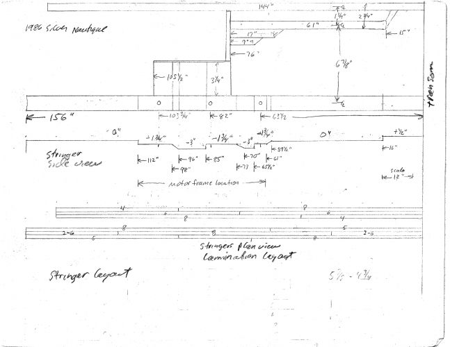
This is the stringer layout for my boat. The old stringers where likely cut from a standard pattern but I’m not sure how tight they followed the pattern. I expect each boat varies a little based on what I’ve seen on this boat. Best if you use your stringers to layout your new stringers. But if you can’t use your stringers, this should get you pretty close for boats like mine. Top of the page is a plan view (looking down) of the secondary stringer, the space for the exhaust hose and the top of the main stringer. The circles are bolt holes in the aluminum engine frame. Below that is a side view of the stringer showing the dips, their locations and depths. The gas tank is shown at + ½” because the floor is a ½” thick and the two aluminum angles under the tank sit basically flush with the top of the floor, making the bottom of the gas tank maybe a ¼” above the floor. 0” elevation is the underside of the floor. Everything is measured from the transom of the boat in line with the thing you are laying out, keeping in mind that the main stringer hits the transom is a bit further aft than the secondary stringer because of the curve in the transom. At the bottom of the page is a plan view of the secondary and main stringers showing the lamination schedule. As you will see in a following post, the secondary stringer is made up of ¼” Coosa laminated together to get to ¾” thickness and the main stringer is made up of ½” Coosa to get to 1 ½” thickness.
EDIT: In the above sketches I put the notches in the stringers to match the original, including the locations of the notches for the engine mount bolts (deepest notches on the sketch). This was a mistake, the front engine mount bolt notches are much longer than needed and the back notches too tight. I have way too much space on the front notches and I had to sand out and then re-glass the front part of the back notches to get a bit more clearance for those bolts. In addition, the front of all the notches are sloped, for no reason I can discern. Better plan is to make the notches run about 1 ½” past the bolt locations in the engine frame and make the ends of the notches vertical with rounded corners at the bottom and top of the vertical cuts. |
|
|
Builder
|
|
|
|
|
andrewmarani
Senior Member
Joined: May-31-2005 Location: Baltimore, MD Status: Offline Points: 214 |
Post Options
Thanks(0)
Quote Reply
Posted: September-19-2023 at 7:04pm |
|
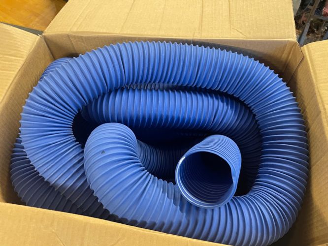
Since i'm closing in on foaming the floor I am also now in need of the hose that gets buried in foam under the front floor. Never liked the cheap plastic stuff installed originally in the boat. Spent some time on the site looking for an answer and McMaster Carr turned up a couple of times but didn't like what I found and it was expensive. Finally turned up the stuff below at Fisheries Supply. https://www.fisheriessupply.com/trident-marine-trident-polyduct-hvac-duct/481-3000 Still expensive at $6.83 a foot but looks nice and is very flexible. 3" Trident Marine Polyduct HVAC Duct.
 |
|
|
Builder
|
|
|
|
|
andrewmarani
Senior Member
Joined: May-31-2005 Location: Baltimore, MD Status: Offline Points: 214 |
Post Options
Thanks(0)
Quote Reply
Posted: September-19-2023 at 6:07pm |
|
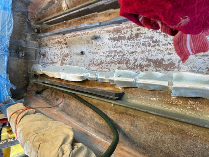
And this is where i'm at as of Sunday. The little narrow strips are installed and filleted into place. Next is trimming the floor to the engine hole. Then spending some time laying out and making the vertical closers that sit on the pieces I just installed and rise to the underside of the coosa floor. The flooring in the picture is just sitting there loose.
 |
|
|
Builder
|
|
|
|
|
andrewmarani
Senior Member
Joined: May-31-2005 Location: Baltimore, MD Status: Offline Points: 214 |
Post Options
Thanks(0)
Quote Reply
Posted: September-19-2023 at 6:00pm |
|
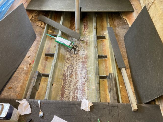
This shows the little supports for that lowered section of floor on either side of the engine. I'm not tabbing them in, just laying down a nice fillet on all sides. The narrow pieces laying on the stringers go on top of the supports. The Coosa leaning against the hull are the pieces of floor next to the engine, fitted to the hull but still need to adjust for the engine hole.
I'm mostly only able to put in an hour here and there right now so time is a factor. I bought more of the Totalboat Thixo, this time in the double tube, which gives a lot more epoxy for the price. Still expensive at $45 a double tube but I had the special gun already and now I can just put a new nozzle on the tube and epoxy without having to spend time mixing stuff and then clean up.
 |
|
|
Builder
|
|
|
|
|
andrewmarani
Senior Member
Joined: May-31-2005 Location: Baltimore, MD Status: Offline Points: 214 |
Post Options
Thanks(0)
Quote Reply
Posted: September-19-2023 at 5:51pm |
|
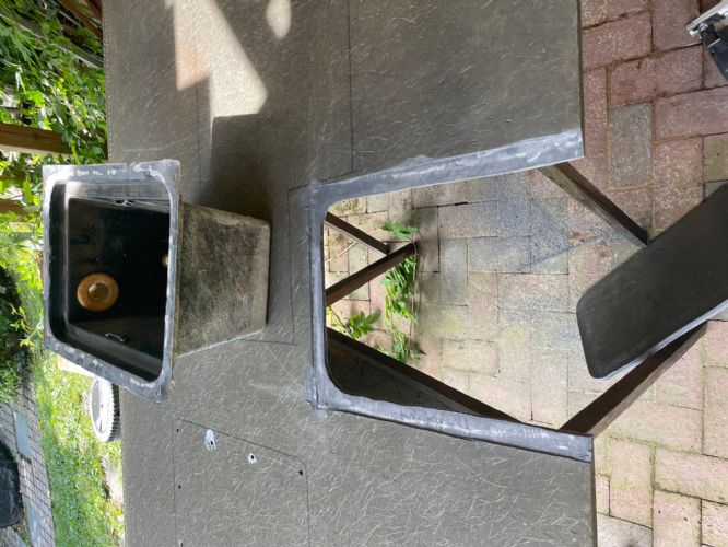
The Coosa floor is mostly cut and fitted. I still have to make the bow piece and do some fitting around the engine hole. This shows the cut out for the battery box. To get the box edges to sit flush with the floor I dished out the Coosa using a Mikita belt sander that takes a 1" belt. Wish I had bought that machine earlier, makes controlled removal and cleanup of fiberglass easy.
 |
|
|
Builder
|
|
|
|
|
andrewmarani
Senior Member
Joined: May-31-2005 Location: Baltimore, MD Status: Offline Points: 214 |
Post Options
Thanks(0)
Quote Reply
Posted: September-19-2023 at 5:46pm |
|
Next up, you can see the ledger I glued to the sides of the boat to catch the edges of the floor. Had plenty of thin Coosa scraps to make up the ledgers. Used some thin flexible wood to hold the ledger in place while the epoxy tightened up. To locate the ledger I used a laser level to draw a black marker line around the hull a 1/2" below where the top of the floor will be and checked to make sure that matched the top of the new stringers.
 |
|
|
Builder
|
|
|
|
|
andrewmarani
Senior Member
Joined: May-31-2005 Location: Baltimore, MD Status: Offline Points: 214 |
Post Options
Thanks(0)
Quote Reply
Posted: September-19-2023 at 5:06pm |
|
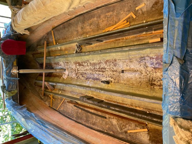
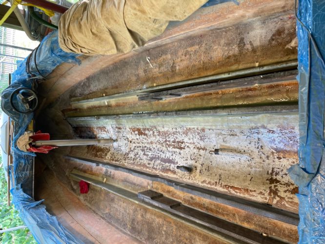
Right main stringer glassed in. you can see all the elevation changes in the left stringer.
 |
|
|
Builder
|
|
|
|
|
andrewmarani
Senior Member
Joined: May-31-2005 Location: Baltimore, MD Status: Offline Points: 214 |
Post Options
Thanks(0)
Quote Reply
Posted: September-19-2023 at 5:05pm |
|
The top of the main stringer has lots of dips in it. this shows the cuts in the glass to get it to lay into the ups and downs. Mostly worked, i'm sure an expert fiberglass dude has some better way of doing this!
 |
|
|
Builder
|
|
|
|
|
andrewmarani
Senior Member
Joined: May-31-2005 Location: Baltimore, MD Status: Offline Points: 214 |
Post Options
Thanks(0)
Quote Reply
Posted: September-19-2023 at 4:57pm |
|
Didn't really realize how long it's been since I posted on this. Life's been doing it's thing: went on vacation out of the country, twice. Had a neck operation, all good, plus I'm 3/16" taller now. I have managed to keep going on the boat, closing in on the need to foam the interior. Posting a series of pictures of the progress.
This shows the rolls of fiberglass ready for the stringers, folded in half to create a crease to make it easier to fit, four for each side. 4" wide first (2" on floor, 2" on stringer) then 6" wide, then 8". The wides rolls are the pieces that fold down over the top, 8" again but only needed four. 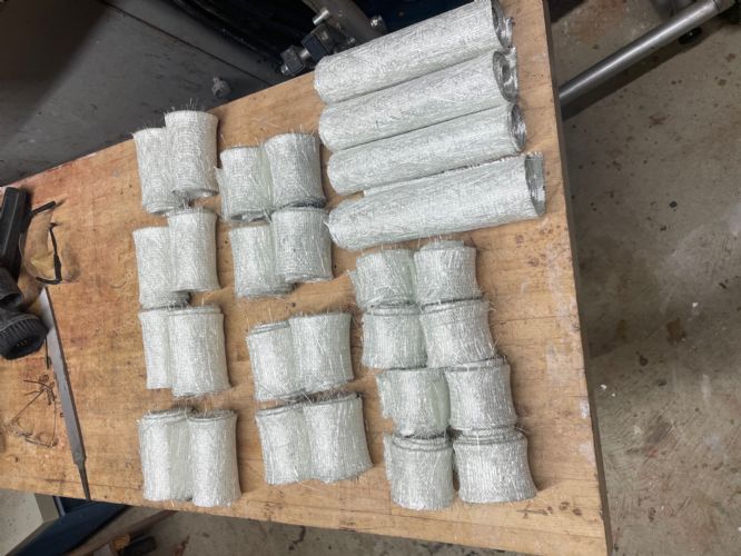 |
|
|
Builder
|
|
|
|
|
Jonny Quest
Grand Poobah

Joined: August-20-2013 Location: Utah--via Texas Status: Offline Points: 2842 |
Post Options
Thanks(0)
Quote Reply
Posted: May-08-2023 at 10:51pm |
|
Looking good Andrew!

|
|
|
Current
2003 Ski Nautique 206 Limited Previous 2001 Ski Nautique Open Bow 1994 Ski Nautique Open Bow Aqua skiing, ergo sum |
|
|
|
|
andrewmarani
Senior Member
Joined: May-31-2005 Location: Baltimore, MD Status: Offline Points: 214 |
Post Options
Thanks(0)
Quote Reply
Posted: May-08-2023 at 8:24pm |
|
Last picture for now, showing the front floor sitting in place for fitting check. You can't really see it in the earlier stringer picture but i've notched the stringers down at each floor joint location so I can run a piece of 3" wide Coosa under the seam between two pieces of flooring to tie the two pieces together when I epoxy them down.
 |
|
|
Builder
|
|
|
|
|
andrewmarani
Senior Member
Joined: May-31-2005 Location: Baltimore, MD Status: Offline Points: 214 |
Post Options
Thanks(0)
Quote Reply
Posted: May-08-2023 at 8:16pm |
|
So take a closer look at the upper side of the floor where the drivers seat base is drawn in. See that short diagonal line on the corner that will be next to the side of the boat? DO NOT run a screw through the drivers seat base in that location! Why, you ask? Well, the hull of the boat is right there on the other side of the floor and people have been know to screw through to the outside of the boat, causing a leak that puzzled them for months until they cut their hand feeling along the bottom of the boat looking for cracks.
That's also why the reinforcing on the underside of the floor is clipped off in that area.
Moving on. Does anyone know where to buy a new battery box? Mine is in reasonable shape except for the top flange, which is wavy as hell. It's going to be very hard getting that thing to sit flat on the floor and take carpet neatly. Rather buy a new one if I can.  |
|
|
Builder
|
|
|
|
|
andrewmarani
Senior Member
Joined: May-31-2005 Location: Baltimore, MD Status: Offline Points: 214 |
Post Options
Thanks(0)
Quote Reply
Posted: May-08-2023 at 8:00pm |
|
Coosa is not a great screw holding material so I'm using T nuts to hold down the drivers seat, the observers seat, the hinges for the engine cover and the hinges for the back seat. You can see the layout of the seats on the upper side of the front section of flooring and you can see the T nuts and the doubled up coosa on the underside. I've also applied a layer of glass to the underside as reinforcing. I still need to cut out the hole for the battery box. Many thanks to va-river-tique for those dimensions, major help.
 I seemed to be pulling the observers seat support out on a regular basis to crawl up under the front for one reason or another. In the earlier floor I installed two machine thread inserts into the plywood floor and used two 3/8" bolts inside the base (with an added wire grab kind of thing that allowed me to remove them by hand) to secure the base to the floor. Same sort of operation now with the Coosa, only i've got T nuts in the Coosa to run the bolts into.  |
|
|
Builder
|
|
|
|
|
andrewmarani
Senior Member
Joined: May-31-2005 Location: Baltimore, MD Status: Offline Points: 214 |
Post Options
Thanks(0)
Quote Reply
Posted: May-08-2023 at 7:48pm |
|
Been a while since I posted on this, life sometimes gets in the way of the best of plans. I glassed in the secondary stringers a month ago or so. I cut and fitted most of the 1/2" coosa for the floor. This weekend I epoxied in the short pieces of stringer that sit next to the mufflers. The coosa is only a 1/2" thick and that didn't seem wide enough for a location that supports both a fixed section of floor and the removable panel next to it so I epoxied another piece of 1/2" about 1 1/2" tall against the short stringer piece to widen it to 1", You can see the clamps holding the second piece in place in a picture. You can't see it in the picture but I cut a 45 on the down edge of that added piece so the glass will wrap down it easily.  |
|
|
Builder
|
|
|
|
|
andrewmarani
Senior Member
Joined: May-31-2005 Location: Baltimore, MD Status: Offline Points: 214 |
Post Options
Thanks(0)
Quote Reply
Posted: March-03-2023 at 4:32pm |
|
If I hadn't used the vacuum set up, I would have used a combination of stainless deck screws and clamps. I was originally worried about not having enough time to epoxy all three layers in one move but my basement was about 60 degrees and I had lots of time once the material was spread thin on the Coosa to adjust the pieces and set up the vacuum rig. So I figure you should have plenty of time to lay up three pieces and run screws into them. Make sure you put epoxy on both mating surfaces. I wet one out with a smooth spreader and then spread epoxy on the other with a fine notched spreader. I put silica adhesive filler in the epoxy to thicken it some.
I've run screws into the Coosa and they take up fine but are easy to over torque and strip out. I would glue up all three layers, then clamp a section tight, run some screws into that section to hold it tight, then move the clamps to the next section and repeat. An alternate would be to set the three layers on a long 2x8 and screw right through the Coosa into the 2x8, once it's set up, pull the screws and your good to go. On the 86', the engine mounts bolt to the aluminum frame that sits on the stringers so no worries about them tearing out. I am NOT planning to run lags down through the frame into the Coosa (like it was originally), instead I plan to through bolt the frame to the stringers from the side. I would not trust heavy uplift loads to a wood type screw in the Coosa. If you don't have the aluminum frame to support the engine mounts, I would cut some holes or a slot down near the bottom of the stringer, put a block of aluminum in there as a load spreader and through bolt down from the engine mount, thorough the stringer, through aluminum block and put a nut and lock washer on it from underneath.
|
|
|
Builder
|
|
|
|
|
blammie
Groupie 

Joined: June-27-2010 Location: Toledo Status: Offline Points: 46 |
Post Options
Thanks(0)
Quote Reply
Posted: March-02-2023 at 4:48am |
|
So I'm also in the process of rebuilding a '68 Barracuda. I have one stringer removed and ran into a snag sourcing new stringer material. I originally was thinking I would use a vertical grain Douglas fir, until I was quoted over $900 a piece for a 2x10x14. I can get by with a 2x8 and shave a little off the price, but probably not enough to make sense. Pretty much, it seems I am priced out of anything with vertical grain. I'm now leaning towards Coosa board, having found a source in the Detroit area, and realizing it is going to be cheaper or comparable to Spruce or DF. One concern I have is the motor mounts. I've read some guys mentioning difficulty keeping screws set in Coosa. Is there any truth here? I'm looking for guidance from guys that have actually been through the process. I was initially thinking two layers of 3/4" with staggered seams for the stringers, but I'm thinking I might mimic Andrew and go with 3 layers of 1/2". It feels like those joints will be stronger. My question is, how do I assemble them? I don't have a vacuum setup, but I do have plenty of clamps. Obviously, I'll resin them together, but should I just clamp, or should I consider screwing them also? and if I screw them, what do you suggest, wood screws, or possibly through bolts? Also I'm wondering about my motor mounts. Should I expect any issues. I am figuring to pre-drill the stringer and secure the mounts with lags, just like I would with wood. Your advice would be much appreciated. The further away I get from wood products, the further I am from my wheelhouse.
|
|
|
|
|
wayoutthere
Senior Member
Joined: February-28-2020 Location: Florida Status: Offline Points: 391 |
Post Options
Thanks(0)
Quote Reply
Posted: February-07-2023 at 5:26am |
Nice work, great idea using coosa |
|
|
|
|
andrewmarani
Senior Member
Joined: May-31-2005 Location: Baltimore, MD Status: Offline Points: 214 |
Post Options
Thanks(0)
Quote Reply
Posted: February-05-2023 at 9:42am |
|
At first I leveled the boat using a 4’ level but I wanted the boat exactly level with no twist when I started epoxying in the stringers.. While trying to figure out a simple way to check for twist in the hull and level the stringers as I cut them to the shape of the hull, I remembered my laser level. The laser has a magnet hanger so I used some small hose clamps to attach a long steel bolt to the back davit hanger, you can see the level and the bolt in the picture. I set the laser at 8” above the old floor level and rechecked the boat for level. No surprise, it wasn’t exactly level and had a slight twist. By the way, what points to measure for leveling front to back is a bit of a guess as the original floor definitely wasn’t flat. I used the 4’ level and a long straight edge to check the sides, from side to side and the laser level to compare points on either side of the bottom working from back to front. The boat is hung from the davit points but I’ve got supports under the back corners and the front roughly at the windshield to take some load off the davits points and stop the boat from rocking when I’m in it working. I adjusted the davit hangers and shimmed the supports until I had the boat hull level by laser. No matter how much I tried, if the hull was level side to side, the top of the sides, side to side just behind the windshield was a ¼” out by the 4’ level. Back of the boat side to side at the top of the sides was level. So the boat was built with a slight twist, not enough to matter and I elected to level the floor to the hull, not the sides. Once the stingers where epoxied in I checked them with the laser. Three where good at 8 ½” below the laser. One secondary was correct in the back but was a ½” high by the time it got to the front. 15 minutes with a belt sander leveled it out to match the others.
|
|
|
Builder
|
|
|
|
|
samudj01
Gold Member

Joined: March-10-2009 Location: NC Status: Offline Points: 933 |
Post Options
Thanks(0)
Quote Reply
Posted: February-05-2023 at 9:31am |
|
Looking good. Thanks for the pics
|
|
|
78 Ski Tique, 72 Skier w/302's, 93 SN w/351 & 17 GS22 w/zr409
Previous - 99 Sport Nautique w/GT40 and 87 Martinique w/351 |
|
|
|
|
fanofccfan
Platinum Member

Joined: December-13-2009 Location: North Bend NE Status: Offline Points: 1722 |
Post Options
Thanks(0)
Quote Reply
Posted: February-04-2023 at 10:06pm |
|
Nice progress. Oh how the pictures help entertain me and others!
|
|
|
2004 196 LE Ski 1969 Marauder 19 1978 Ski
|
|
|
|
|
andrewmarani
Senior Member
Joined: May-31-2005 Location: Baltimore, MD Status: Offline Points: 214 |
Post Options
Thanks(0)
Quote Reply
Posted: February-04-2023 at 5:20pm |
|
The current state of affairs. Primary and secondary stringers epoxied into place but not glassed in. That section of deck is only installed temporarily, as is the engine frame. Working on fitting the decking to the hull and laying out the seats and engine cover attachment points so I can reinforce those locations. I need the scraps left from fitting the deck to make up the stringer build outs at the engine and the exhausts. Tomorrows project is to start cutting up those scraps to into the stringers.
  |
|
|
Builder
|
|
|
|
|
andrewmarani
Senior Member
Joined: May-31-2005 Location: Baltimore, MD Status: Offline Points: 214 |
Post Options
Thanks(0)
Quote Reply
Posted: February-04-2023 at 5:11pm |
|
Secondary stringers being epoxied into place.
 |
|
|
Builder
|
|
|
|
|
Post Reply
|
Page <1234> |
 Tweet
Tweet
|
| Forum Jump | Forum Permissions You cannot post new topics in this forum You cannot reply to topics in this forum You cannot delete your posts in this forum You cannot edit your posts in this forum You cannot create polls in this forum You cannot vote in polls in this forum |


 Topic Options
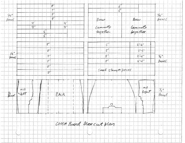
 andrewmarani wrote: