 Boats For Sale:


Removing Protec & Throttlebody, installing carb |
Post Reply 
|
Page <1234> |
| Author | |
Erikgundy98 
Groupie 
Joined: February-09-2021 Location: Vancouver, wa Status: Offline Points: 62 |
 Post Options Post Options
") Thanks(0) Thanks(0)
 Quote Reply Quote Reply
 Posted: April-20-2021 at 9:04pm Posted: April-20-2021 at 9:04pm |
|
Getting into this fuel line replacement, is there a fuel filter down in the tank? I don’t have on in-line (I’ve just replaced the fuel separator), and curious what any of you have added fuel filters in-line.
My tank has a bottom with a good sized - about 4” diameter- (assuming it is the bottom of the float & fuel pickup) section in the middle that is lower than the rest of the tank. Curious if I need to remove tank if there’s a filter in there. That would be one bugger of a place to put a filter! Thanks! Erik |
|
 |
|
|
KENO
Grand Poobah 
Joined: June-06-2004 Location: United States Status: Offline Points: 10652 |
Post Options
Thanks(0)
Quote Reply
Posted: April-21-2021 at 8:08am |
|
There's most likely a screen at the end of the suction line to keep the big chunks from getting into the anti siphon valve unless somebody previously removed it.
Besides whatever it's real purpose is, a secondary unwanted, undesired purpose of that little sump section is to make rudder, tiller arm access next to impossible without removing the tank  |
|
|
|
|
Erikgundy98
Groupie
Joined: February-09-2021 Location: Vancouver, wa Status: Offline Points: 62 |
Post Options
Thanks(0)
Quote Reply
Posted: April-21-2021 at 10:49am |
|
Thanks. So, is it recommended to add a fuel filter in-line? I see newer boats have replacement ones available... I guess I originally thought the separator worked as a filter...
Any advice on where you guys put yours? I would assume after separator, before fuel pump... although I hate having additional set of clamps on the fuel line if it is not recommended. |
|
|
|
|
Gary S
Grand Poobah

Joined: November-30-2006 Location: Illinois Status: Offline Points: 14096 |
Post Options
Thanks(0)
Quote Reply
Posted: April-21-2021 at 11:23am |
|
Usual suspects have this under control but I'm curious as to what it is that your calling a separator Eric.
|
|
|
|
|
Erikgundy98
Groupie
Joined: February-09-2021 Location: Vancouver, wa Status: Offline Points: 62 |
Post Options
Thanks(0)
Quote Reply
Posted: April-21-2021 at 11:38am |
|
Fuel/water separator. https://www.nautiqueparts.com/product/fuel-water-separator-kit/
Yeah I guess I’m not a usual suspect :) |
|
|
|
|
Gary S
Grand Poobah
Joined: November-30-2006 Location: Illinois Status: Offline Points: 14096 |
Post Options
Thanks(0)
Quote Reply
Posted: April-21-2021 at 12:01pm |
|
Your good with what you have - that "separator" is a filter
|
|
|
|
|
Erikgundy98
Groupie
Joined: February-09-2021 Location: Vancouver, wa Status: Offline Points: 62 |
Post Options
Thanks(0)
Quote Reply
Posted: April-21-2021 at 12:34pm |
Thanks Gary! |
|
|
|
|
nobrainsd
Senior Member 
Joined: August-13-2015 Location: San Diego Status: Offline Points: 157 |
Post Options
Thanks(0)
Quote Reply
Posted: April-21-2021 at 5:28pm |
|
As I am coming up on fuel/water separator cartridge change (it is rusting in spots), I have to ask, is there any reason to not go with a 10 micron filter replacement over the 21 micron filter I got in that exact same kit from SkiDim?
|
|
|
|
|
Erikgundy98
Groupie
Joined: February-09-2021 Location: Vancouver, wa Status: Offline Points: 62 |
Post Options
Thanks(0)
Quote Reply
Posted: April-21-2021 at 6:02pm |
|
Anybody have a picture of the bracket that holds the 60A breaker and starter relay? Thanks!
|
|
|
|
|
KENO
Grand Poobah
Joined: June-06-2004 Location: United States Status: Offline Points: 10652 |
Post Options
Thanks(0)
Quote Reply
Posted: April-21-2021 at 6:10pm |
|
The picture in the link below is the kit you bought from Nautiqueparts. The bracket is next to the black plastic cover and has a couple of black wires laying on it in the picture It mounts using the top two bolts holding the bellhousing to the block and the starter relay bolts to that. The little bracket above it in the picture bolts to the bigger bracket and holds the breaker and resistor
|
|
|
|
|
Erikgundy98
Groupie
Joined: February-09-2021 Location: Vancouver, wa Status: Offline Points: 62 |
Post Options
Thanks(0)
Quote Reply
Posted: April-21-2021 at 6:21pm |
Yeah, I am getting it connected, and yet I’m not sure how the 60A breaker connects to this bracket. Nor how that black plastic cover is held down/in place. That’s the kind of picture I was looking for... was someone who already mounted theirs, & what the end product looks like. Assuming we’re all installing the same setup, it seems like it should be a tad more intuitive :) If I need to drill my own / aka if this kit works for many years/ that might explain the not exact bolt holes. Yes the bell housing bolts match, but ... the rest seems like I might need to modify. But I just haven’t seen what the end product looks like... :) Thanks. -not usual suspect :) |
|
|
|
|
KENO
Grand Poobah
Joined: June-06-2004 Location: United States Status: Offline Points: 10652 |
Post Options
Thanks(0)
Quote Reply
Posted: April-21-2021 at 6:29pm |
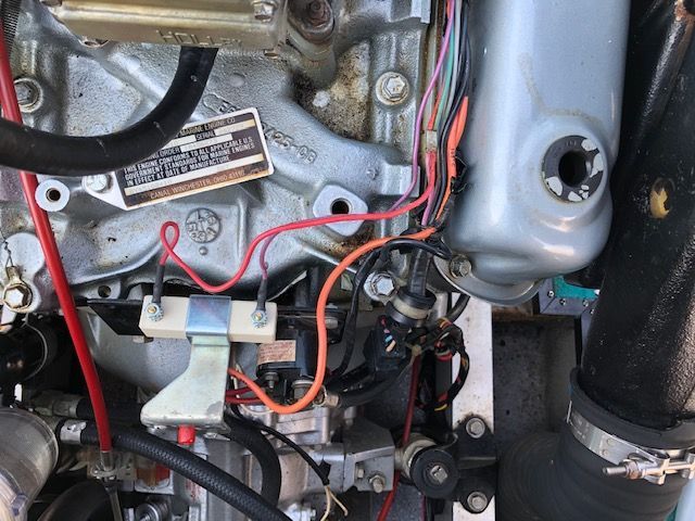
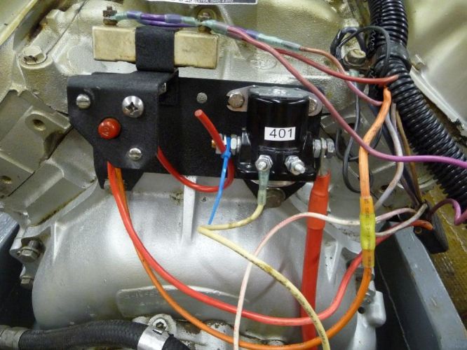 Well, why didn't you say so? It's really not intuitive at all. Here's a picture from the internet, that should give you an idea maybe . Ignore the "not too pretty" wiring and the different style relay. Your relay goes in the same spot though. |
|
|
|
|
KENO
Grand Poobah
Joined: June-06-2004 Location: United States Status: Offline Points: 10652 |
Post Options
Thanks(0)
Quote Reply
Posted: April-21-2021 at 6:43pm |
|
And here's one from CCF showing the breaker bracket more centered, then the plastic piece should be intuitive after that
The Red breaker button fits in the hole in the plastic cover
 |
|
|
|
|
Erikgundy98
Groupie
Joined: February-09-2021 Location: Vancouver, wa Status: Offline Points: 62 |
Post Options
Thanks(0)
Quote Reply
Posted: April-21-2021 at 7:18pm |
Thank you so much! This is exactly what I’ve been looking for, and I bet prior to the ranch somewhere hacked… I bet I would’ve been able to find that on my own. I just read through these posts, that appear to possibly have pictures with them, but don’t see very many pictures… And I don’t know the right language or vocabulary to search for some of these things. I really appreciate these pictures! |
|
|
|
|
KENO
Grand Poobah
Joined: June-06-2004 Location: United States Status: Offline Points: 10652 |
Post Options
Thanks(0)
Quote Reply
Posted: April-21-2021 at 8:08pm |
|
Eric
I'm just a search geek or search dork or fill in whatever word you want to..........or I go take my own pictures If you use your favorite search engine like say Google and type in "correctcraftfan starter relay" knowing that the relay bolts to the plate, when the results come up click on "images" and you get a bunch of photos, some pertinent, some not. In this case the picture I posted was found that way on the Mastercraft website since Google is so smart. You can type in correctcraftfan followed by whatever you're looking for and find a lot of stuff that way. You can also veer way off course, but you'll learn a lot along the way. In the case of the gone forever photos from CCF, sometimes you'll see them on a Google search on the images page. You can also type the name of the person like for example correctcraftfan keno distributor if you know the screen name of the guy whose post you're looking for It's a finely honed skill that I learned from a 13 year old  PS........there are probably better ways, but this works pretty good for me
|
|
|
|
|
Gary S
Grand Poobah
Joined: November-30-2006 Location: Illinois Status: Offline Points: 14096 |
Post Options
Thanks(0)
Quote Reply
Posted: April-21-2021 at 9:05pm |
I don't think there is any reason that you can't. The filter PCM uses in their FCC's is a 10
|
|
|
|
|
Erikgundy98
Groupie
Joined: February-09-2021 Location: Vancouver, wa Status: Offline Points: 62 |
Post Options
Thanks(0)
Quote Reply
Posted: April-25-2021 at 7:27pm |
|
I upgraded the alternator to the 100 Amp alternator, with new cable from alternator to starter relay.
Since the cable has a 100 amp fuse, I’ll bypass the 60a breaker with this cable. I was going to eliminate the 60a breaker, but the power (red wire) needs something to connect to (in the diagram it comes off the breaker). The terminals on the back of the breaker are too small for the large eye on the new cable anyway. I assume this is correct. Correction (if necessary) appreciated! :) |
|
|
|
|
KENO
Grand Poobah
Joined: June-06-2004 Location: United States Status: Offline Points: 10652 |
Post Options
Thanks(0)
Quote Reply
Posted: April-25-2021 at 7:57pm |
|
Sounds OK to me.
Big cable (of some not mentioned size" with 100 amp fuse going to the A terminal on the relay lets the alternator charge the battery at 100 amps if necessary and leaving the 60 amp breaker in place with the red wires attached will protect the wiring going up to the dash which isn't big enough for 100 amps. So.........what size is the new alternator output wire? And, is it safe to assume that you won the battle with the fuel pump?
|
|
|
|
|
Erikgundy98
Groupie
Joined: February-09-2021 Location: Vancouver, wa Status: Offline Points: 62 |
Post Options
Thanks(0)
Quote Reply
Posted: April-25-2021 at 8:15pm |
|
Yep. Won the battle w/ fuel pump. :)
https://www.nautiqueparts.com/product/fuse-link-circuit-breaker-to-starter-100-amp-fused-wire-pcm-gm-engines-from-2002-on-r153018a/ doesn’t list size. I don’t know the gage wire. But it’s bigger than the old one, and smaller than the ones coming from battery and going to starter. I just can’t believe the diagram that came with this wiring harness. The new wiring harness has white wires, yet I don’t know what the white connect to. Looking for white connections, If you look at the diagram it says “3” connects to white/red, but next to the image of the “3 wire”, it says white. https://drive.google.com/file/d/15SbXM1X_gZkJpnw50y_JOg1MINMcFnfl/view?usp=drivesdk Current fight is this wiring harness ;) At the rear of the engine, just off the plug, there are two groups of wires: approx 14ga red and 16ga purple wire, and a larger red (10ga maybe) and 16ga white connected to many more white of same ga. Assuming red and purple go to resistor; 10ga red goes to 60A breaker. But those white wires. Has anyone else installed this harness, on a ‘94 SN? https://drive.google.com/file/d/1THnamS_-nEIdq35MTxASzsNO5I2eC-Lv/view?usp=drivesdk I installed the resistor, but do I have to cut the ends of the purple and red to connect to the resistor? Can’t believe in their “kit” I would need to do this. Hmmm Thanks for the help. Erik |
|
|
|
|
Erikgundy98
Groupie
Joined: February-09-2021 Location: Vancouver, wa Status: Offline Points: 62 |
Post Options
Thanks(0)
Quote Reply
Posted: April-25-2021 at 8:48pm |
|
I’m wondering how many wires on this harness are not necessary, if you get rid of the throttle body....
|
|
|
|
|
KENO
Grand Poobah
Joined: June-06-2004 Location: United States Status: Offline Points: 10652 |
Post Options
Thanks(0)
Quote Reply
Posted: April-26-2021 at 5:48am |
In your first linked picture where you ask "what is this"..........it's the neutral safety switch. On your PCM 40A transmission, it's at the top front and you'll have a white wire from your harness coming from pin 3 going to one terminal and another white from the other terminal to the "S" terminal on the start relay. The switch looks like this. It doesn't matter which terminal you hook which wire to. It's basically an open/closed switch, that's open when the transmission is not in neutral and when in neutral it's closed so that when you turn the key, power will be supplied through it to the "S" terminal.  The red and purple should hook to the resistor like you said. Some resistors have spade type terminals with a little hole in each spade for a small machine screw and nut to hold the wire to the resistor terminal, others use spade type connectors, so maye you have a little modifying of the ends of the wires to hook things up. The TRBenj diagram earlier in this thread is your best friend right now It shows red/yellow instead of white to the neutral safety switch. PCM used both colors over the years.I seem to think that he made his colorful diagram because the PCM was a "little" harder to follow and make sense of. Hang in there, you're making progress |
|
|
|
|
Erikgundy98
Groupie
Joined: February-09-2021 Location: Vancouver, wa Status: Offline Points: 62 |
Post Options
Thanks(0)
Quote Reply
Posted: May-02-2021 at 7:52pm |
|
A few questions:
This green wire, at wiring harness plug, I can’t find what it was connected to, and I can’t find it on the wiring diagram. https://drive.google.com/file/d/171BUZqmMYLa8awqvDwlBUiyBBMQXWK8a/view?usp=drivesdk Does it not connect to anything after this upgrade? Question 2- the ground for the carburetor choke. Is this little black wire, that came on the carb, is it now grounded to the carb, in turn grounding to the block? Or should I pull the small wire, and connect the 14ga ground wire here (in picture) to the choke in its place? I will have to change the connector, as this one on the harness is a male, and so is the choke. https://drive.google.com/file/d/16BAhkOzKTfLGfVO_2GOTRgk15ZieQpai/view?usp=drivesdk I also upgraded the alternator, so with it came a 6ga wire. Recommendations on where it connects to the block? And Nautique parts instructed me to connect the red eyelet of the alternator plug to the positive stud on the alternator. Seems very redundant to me. Anyone else get this advice? https://drive.google.com/file/d/1ZGMmLSQ4llR0s78QOIDjYSDJBTJT7euK/view?usp=drivesdk Thanks!! Erik |
|
|
|
|
KENO
Grand Poobah
Joined: June-06-2004 Location: United States Status: Offline Points: 10652 |
Post Options
Thanks(0)
Quote Reply
Posted: May-02-2021 at 8:32pm |
|
Question 1 The green wire goes to the warning light on the dash for low oil pressure or high water temperature, but since the new harness has no connections for that, you can leave it disconnected or run wires to your oil pressure switch and coolant temp switch.
Easiest is to leave it disconnected and tell yourself that real men use the gauges and don't need no stinkin' warning light Alternately, people have done things like wire the switches back to that Green wire to retain the warning light. If you want to do that, continue the green wire to each switch. Question 2 Read the thread in the link below, you can ground it either way (Second picture didn't work, need some kind of permission to view it.) Question 3 I think I'd do what they say, it provides the voltage sensing signal to the alternator. |
|
|
|
|
Erikgundy98
Groupie
Joined: February-09-2021 Location: Vancouver, wa Status: Offline Points: 62 |
Post Options
Thanks(0)
Quote Reply
Posted: May-03-2021 at 8:58pm |
|
So I think I’m done wiring.
Thank you Keno (& others) for all your help. https://drive.google.com/file/d/1amC-ZWi_QdHQoKBMDuU0XjZKVNmD3EBs/view?usp=drivesdk I am now moving on to installing the replacement steering cable. But I really want to turn it over (engine) just to see if the wiring is all finished, good, & correct. Is it advisable to put the intake hose in water, even if just turning it over to check if all wiring is correct? Not going to set timing yet. But, to do so, I would install muffler to keep water out of the boat. I haven’t installed my muffler yet, as I like the room for accessing steering cable. I guess I’ll just do the cable and turn it over another night. Anything “burning” (or advisable) to do while I’m here without the muffler in? Boat has 1100 hrs. Transmission fluid is a nice red color, & is full. Not sure last time it was changed. Hesitating on “doing more” as I already bit off a lot. But I know, the last thing I want to do is burn up the tranny. Thanks again Erik |
|
|
|
|
Gary S
Grand Poobah
Joined: November-30-2006 Location: Illinois Status: Offline Points: 14096 |
Post Options
Thanks(0)
Quote Reply
Posted: May-03-2021 at 9:27pm |
|
I vote for doing it now while the muffler is out you'll just have that much more room. If your only going to turn it over just remove the belt to the raw water pump
|
|
|
|
|
Erikgundy98
Groupie
Joined: February-09-2021 Location: Vancouver, wa Status: Offline Points: 62 |
Post Options
Thanks(0)
Quote Reply
Posted: May-03-2021 at 9:50pm |
|
Thanks Gary!
I thought this past would be easy- but, spark plugs... from #1, are they going clockwise or counterclockwise? I have a LHR motor I don’t have an example to go from, and I can’t seem to find result in a search that will show me. I know the order for this is 13726548... but cc or ccw? Stupid question. Sorry guys. I’ll keep searching, but if someone finds it before me, thanks a lot!! |
|
|
|
|
Jonny Quest
Grand Poobah

Joined: August-20-2013 Location: Utah--via Texas Status: Offline Points: 2843 |
Post Options
Thanks(0)
Quote Reply
Posted: May-03-2021 at 10:35pm |
|
Your SBF distributor runs counter-clockwise.
|
|
|
Current
2003 Ski Nautique 206 Limited Previous 2001 Ski Nautique Open Bow 1994 Ski Nautique Open Bow Aqua skiing, ergo sum |
|
|
|
|
Erikgundy98
Groupie
Joined: February-09-2021 Location: Vancouver, wa Status: Offline Points: 62 |
Post Options
Thanks(0)
Quote Reply
Posted: May-03-2021 at 10:42pm |
Thank you guys. |
|
|
|
|
Jonny Quest
Grand Poobah
Joined: August-20-2013 Location: Utah--via Texas Status: Offline Points: 2843 |
Post Options
Thanks(0)
Quote Reply
Posted: May-03-2021 at 10:58pm |
|
Perhaps I should clarify...the rotor turns counter-clockwise.
|
|
|
Current
2003 Ski Nautique 206 Limited Previous 2001 Ski Nautique Open Bow 1994 Ski Nautique Open Bow Aqua skiing, ergo sum |
|
|
|
|
KENO
Grand Poobah
Joined: June-06-2004 Location: United States Status: Offline Points: 10652 |
Post Options
Thanks(0)
Quote Reply
Posted: May-04-2021 at 6:06am |
|
And here's the visual example for your normal rotation 351w  |
|
|
|
|
Post Reply
|
Page <1234> |
 Tweet
Tweet
|
| Forum Jump | Forum Permissions You cannot post new topics in this forum You cannot reply to topics in this forum You cannot delete your posts in this forum You cannot edit your posts in this forum You cannot create polls in this forum You cannot vote in polls in this forum |


 Topic Options
 Gary S wrote: