Removing Protec & Throttlebody, installing carb
Printed From: CorrectCraftFan.com
Category: General Correct Craft Discussion
Forum Name: General Discussion
Forum Discription: Anything Correct Craft
URL: http://www.CorrectCraftFan.com/forum/forum_posts.asp?TID=49747
Printed Date: April-29-2024 at 4:41am
Topic: Removing Protec & Throttlebody, installing carb
Posted By: Erikgundy98
Subject: Removing Protec & Throttlebody, installing carb
Date Posted: April-13-2021 at 6:19pm
|
I am installing the distributor, after removing the old wiring harness, and am stuck on how to find TDC when I dont actually have a distributor currently installed (the ProTec ignition is almost all uninstalled, but the instructions on the new (Nautique Parts) instructions for moving from Protec to Distributor says to set engine to TDC. Do you have a strategy to do so without removing the valve cover to look at the valves? Thanks! Erik |
Replies:
Posted By: 8122pbrainard
Date Posted: April-13-2021 at 6:45pm
|
Place your thumb over the #1 cylinder spark plug hole, crank the engine over and when the compression stops you'll be close. ------------- /diaries/details.asp?ID=1622" rel="nofollow - 54 Atom /diaries/details.asp?ID=2179" rel="nofollow - 77 Tique 64 X55 Dunphy Keep it original, Pete < |
Posted By: KENO
Date Posted: April-13-2021 at 7:42pm
|
What's that old saying about "close is only good enough in horseshoes and hand grenades" ? Assuming that you can see the timing marks on your harmonic balancer, you'll need a ratchet wrench, a short extension and a 15/16 socket to fit the bolt holding the balancer to the crankshaft, so you can turn the engine in the normal direction of rotation.(in your case, clockwise while you're looking at it from the front) If you take all the plugs out, it will be a lot easier to turn the engine over (and you can check their condition at the same time) Then you turn the engine with the wrench and put a thumb over the #1 spark plug hole and eventually you'll feel some pressure building up against your thumb. While this is happening, look at the timing pointer and the timing marks on the balancer As the pressure continues to build, you'll see the TDC mark on the balancer line up with the pointer and you're now at TDC on the compression stroke.. Now that you're at TDC on the compression stroke, you can install the distributor
 |
Posted By: TRBenj
Date Posted: April-13-2021 at 7:43pm
|
One usually lines up the TDC mark (0°) on the balancer with the timing pointer. As Pete implied, you’ll want to set it to TDC on the compression stroke, which can be found as he describes (plus lining up the aforementioned timing marks). Dammit KenO |
Posted By: KENO
Date Posted: April-13-2021 at 7:48pm
Damn what? I guess we both figured that somebody had to clear up Pete's info a little bit |
 TRBenj wrote:
Posted By: Erikgundy98
Date Posted: April-13-2021 at 7:48pm
|
I feel so stupid. Thanks for the advice! Worked perfect. I was holding my finger over #5, which has good pressure too (not that it matters), but I was so confused why the balancer (didnt know the name of that) with the timing pointer. Once I found that I was on the wrong side of the engine, when I found pressure building on #1, sure enough the pointer was right at T/C on the timing marks. Thanks guys! I hate asking stupid questions, but after everything I was reading said to "find TDC" and it has been a few years since I have had to time my Vanagon, thus a few years since I have read my manual and really gotten into an engine :) I really appreciate the help. On to putting in the distributor... :) Erik |
Posted By: KENO
Date Posted: April-13-2021 at 7:56pm
| You must be swapping to a carburetor with their kit too? |
Posted By: Erikgundy98
Date Posted: April-13-2021 at 8:29pm
| Yes I am. I’m about to go look at the stickeys to see if there is a good write up on this. I saw some before I started, but not many with great picture. It’s the little things I don’t want to mess up. |
Posted By: KENO
Date Posted: April-14-2021 at 7:50am
|
From another thread, it sounds like you're having issues with the retro fit kit wiring and the instructions. The kit you bought comes with a complete engine side wiring harness to replace what's there now (or at least it should have). Are the instructions hand scribbled on a dirty napkin or maybe something a little better? You must have a diagram or instructions for hooking up the Mallory MBI distributor and ballast resistor that comes in the kit I assume. The fuel side consists of removing the throttle body, installing the carburetor along with a mechanical fuel pump and new fuel line to the carburetor from the pump. It'd be good to check the fuel line from the tank to the pump too, if it's the original. There never has been much of a writeup on the carb swap that I can remember and lots of pictures have disappeared from CCF due to "issues" last summer. If you need some directions or a diagram for the ignition side of things, something could be posted
|
Posted By: Erikgundy98
Date Posted: April-14-2021 at 6:25pm
|
Thanks! I am doing just what you said. I am stuck on the list where it says “•TRANSFER STARTER RELAY (I can do this) AND CIRCUIT BREAKER TO NEW BRACKET ...” I don’t know what circuit breaker they are talking about. Thanks for the help! I got TDC... ready to install wires, but I guess I will start with the wiring harness and see what is needed from the old stuff... I’ll probably figure out this “circuit breaker”... but it’s got me stumped |
Posted By: 8122pbrainard
Date Posted: April-14-2021 at 6:44pm
------------- /diaries/details.asp?ID=1622" rel="nofollow - 54 Atom /diaries/details.asp?ID=2179" rel="nofollow - 77 Tique 64 X55 Dunphy Keep it original, Pete < |
Posted By: Erikgundy98
Date Posted: April-14-2021 at 7:00pm
|
There are 3 of those on mine. I imagined they were for remote starting... but 3? Thanks. Did you (would you) transfer all 3? |
Posted By: 8122pbrainard
Date Posted: April-14-2021 at 7:34pm
|
Erik, Didn't you get any wiring diagram with it? Here's Tim's that may help.: 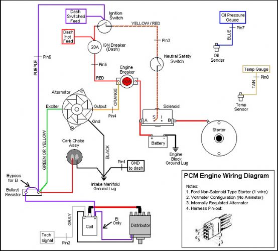 ------------- /diaries/details.asp?ID=1622" rel="nofollow - 54 Atom /diaries/details.asp?ID=2179" rel="nofollow - 77 Tique 64 X55 Dunphy Keep it original, Pete < |
Posted By: KENO
Date Posted: April-14-2021 at 7:50pm
The only breaker of the 3 that you keep is the 50 amp breaker for the conversion. The other 2 go into your "spare parts" collection. If you go to the thread in the link below, when you get to the last post, there is a good explanation of the wiring. http://www.planetnautique.com/vb5/forum/nautique-topics/maintenance-technical-discussion/11439-protec-ignition-conversion-to-mallory-electronic-ignition" rel="nofollow - link And here's a slightly different diagram than what Pete posted, it's been corrected to show how the choke, ballast resistor supply and alternator excitation are connected under the tape in the harness and not at the ballast resistor. It also shows the correct wiring for the solenoid and the starter assuming you have a PMGR starter which PCM started using in 93 You'll have to figure out how to enlarge it and rotate it or print it and enlarge it.  If you combine the linked thread and the picture, things will make a lot more sense.  PS If anybody is wondering about the changes to the TRB diagram, they're based on a completely untaped wiring harness I have hanging on the wall. The TRB diagram gets the point across, but the connections are buried in the harness and you'll get confused just like the guy on Planet Nautique in the linked thread
|
Posted By: KENO
Date Posted: April-14-2021 at 8:19pm
And this probably came with the kit, but if not, it's how the Mallory MBI distributor in your kit is wired |
Posted By: Erikgundy98
Date Posted: April-15-2021 at 1:03am
|
The distributor absolutely did not come with a picture like this. Thank you for this! Thanks for all the links and advice. My wiring harness (from Nautique Parts) is daunting, and I am worried that there are way more wires I took off, than this new one has that I am putting back on. And while there was a diagram (similar to the color one you included above), it was a copy of a copy of a copy, and NP said it is all they have. So thank you a lot for your "Much better" drawings. I really appreciate yours! So, I just took off the throttle body, but is the riser (1" thick riser that the breather tube from the port valvecover attaches to, and was under the throttlebody), is this part of the throttle body, and thus gets removed? Or does it remain, and the new carburetor goes on top of the 1" ... it looks like the new carburetor could go on this, or straight on the engine without it? These are the little things I just dont know, that I dont want to make mistakes leaving behind, when it should be removed. The studs look like if I removed the riser, the studs would be much too long for the carburetor, but I am just not sure.
Thanks for the above links, pictures and advice. And thanks again in advance. Erik |
Posted By: KENO
Date Posted: April-15-2021 at 6:41am
|
Thank TRBenj for the wiring diagram, I just modified it a little to show how the wires hook together inside the harness. In your case it makes things easier. If you look at the colors on the diagram and the colors of the wires in the harness, you'll know for example that the light Blue wire goes to the oil pressure sending unit,Tan goes to the water temperature sending unit, Orange is the output from the alternator to the 50 amp breaker that you're reusing. Just label each temporarily and it'll be easier to get it all wired right. Pay attention to the pin numbers for the 8 plug connector also to help figure things out. You have extra wires on the harness you removed because it was more complicated with the Protec and throttle body. People who have replaced the protec with a DUI distributor and didn't get a kit with a new harness, have usually cut and taped over the extra wires and had to add things like a wire for power to the choke.. Your new harness works and is easier. The spacer should stay in place, it gives a spot for the PCV hose to hook into. Some carburetors will have a spot for the hose to hook into and some don't. Even if your carburetor has a spot for the hose, keep the spacer and cap the extra hose connection, otherwise you'll have a giant vacuum leak.
|
Posted By: KENO
Date Posted: April-15-2021 at 6:50am
|
The distributor wiring schematic came from the link below for the same kit you bought. http://www.myinboardmarine.com/products/retro-kit-protec-pcm-ford-left-hand-351-factory-original-pcm-rk107025a" rel="nofollow - link
I guess they don't make a copy of a copy of a copy, they give you a nice clear easy to read picture The TRBenj diagram was "home grown" here on CCF and gets referenced a lot cuz it good and easy to follow. There are a couple different versions of it. It shows up on a lot of different websites and in printed versions stuffed into somebody's toolbox etc. |
Posted By: Erikgundy98
Date Posted: April-18-2021 at 2:07am
|
This definitely didn’t come with my kit. Wish it did. Thanks for this. I’ll be working on it tomorrow. I installed the carburetor yesterday, but getting the new mechanical fuel pump in is a real chore. Since there is pressure on the lever, even after turning the engine to a position where it was at its minimal pressure, in order to line up the bolt holes, it’s one heck of a feat to get. Any advice? I thought about studs and nuts as the studs can be in first which could help with alignment. Or have I not turned the engine enough to get to a location where the lever on the manual fuel pump is not under pressure? Also, does anyone have a picture of the return fuel line / top of engine? I don’t know where the return fuel line (to tank) now attaches. Thanks again! Erik |
Posted By: KENO
Date Posted: April-18-2021 at 10:06am
|
How long are the bolts that you're using? Since you're replacing a blocking plate that's a lot thinner than a fuel pump, if you're using the original bolts they're too short to make your life easy The bolts should be 1 1/2 inches and with a lockwasher under the head, that leaves enough bolt length to get a good push on the pump with one hand and get one bolt started, then go to the other bolt, get it started and then tighten evenly a little on both bolts till the pump is tightened down. You could use a stud or longer bolt for the first bolt to make it easier and then put in the right length bolt in the end. Some people have used studs and left them installed. It like a lot of other things.............it's not too hard to do after the first time you do it (but the first time can be a killer) If the engine is rotated 1 full turn past TDC on #1 it's a lot easier to install (least amount of pressure on the arm)
|
Posted By: KENO
Date Posted: April-18-2021 at 10:09am
Do you mean, "what do you do with the old fuel return line from the throttle body?" Or do you mean "where do you hook the hose from the 1/4 inch tubing fitting on the fuel pump to?"
|
Posted By: Jonny Quest
Date Posted: April-18-2021 at 10:22am
|
Erik: The ProTec with throttle-body fuel injection used an electronic fuel pump with a return fuel line to the tank. That return line is no longer needed with a mechanical fuel pump. When I did the ProTec-to-carburetor conversion, I cut the return fuel line near the tank and then inserted a plug and used a hose clamp to ensure a good seal. Installing mechanical fuel pump -- yes, getting the actuator arm to "seat" in position can be a p-i-t-a at times. Rotating the engine in small increments may enable you to engage the actuator arm a bit easier. Take out the spark plugs and put a large socket on the harmonic balancer up front. Then, using a breaker bar or large ratchet, you can turn the engine to find the "sweet spot" for installation. The threaded stud option may also help. Try using just 1 threaded stud as a guide and to hold the pump while you install the bolt in the other side. Then you can remove the stud and install the other bolt. JQ ------------- Current 2003 Ski Nautique 206 Limited Previous 2001 Ski Nautique Open Bow 1994 Ski Nautique Open Bow Aqua skiing, ergo sum |
Posted By: Erikgundy98
Date Posted: April-18-2021 at 10:45am
|
Sorry, yes I see how to connect the fuel line into the carb from the new mechanical fuel pump, but on the throttle body, the fuel in, and return line to the fuel tank were right next to each other (formed hard lines). I know the line from the old fuel pump is now to be removed, but not sure what to do about that 2nd line. Assuming both old hard lines get deleted, but where on the carb (if at all) does a 2nd line (return line I assume) get connected? I notice on fuel injected cars, I have this return fuel line to the tank. But in a different life (before kids), on my old vw’s Pict 34 carburetor (70 Ghia, 71 westy, 74 bug) I don’t remember the presence of this return line. How does the throttlebody to carb conversion deal with this? Thank you again for your advice, knowledge, and insight! |
Posted By: Erikgundy98
Date Posted: April-18-2021 at 10:51am
|
Ha! Thanks for the fuel line advice! I wondered! I didn’t think it was going to connect. That fuel pump is my nemesis right now! Glad to see it’s not just me. Im so glad to have you guys. Once I’m done with this, I’ll definitely offer advice like you all are :) Did you all add gasket sealer to either the carb or fuel pump gasket? I saw a guy on YouTube add it when I was searching for “how to get that PITA fuel pump” on. But i never did on my old carbs nor fuel pump on the vw’s. Thanks! |
Posted By: Jonny Quest
Date Posted: April-18-2021 at 12:09pm
|
I used a carb sealing plate and good quality gaskets. No gasket sealer for me. Carb sealing plate from Jegs - Part Number: 555-15442 QuickFuel carb gaskets - Part Number 8-102QFT for open style and Part Number 8-1105QFT for the 4-hole style
JQ
------------- Current 2003 Ski Nautique 206 Limited Previous 2001 Ski Nautique Open Bow 1994 Ski Nautique Open Bow Aqua skiing, ergo sum |
Posted By: KENO
Date Posted: April-18-2021 at 1:59pm
|
Here's a picture of a Carter marine fuel pump and a Holley carburetor. Along with hooking up whatever you decide to use for a fuel line from the pump to the carburetor, you also should be running a piece of clear tubing between the nipple on the fuel pump and the nipple on the carburetor. In the picture they both have a Red cap to show where they are. That line is so that if your fuel pump diaphragm cracks and fails, fuel will be visible in that line and it will be dumping into the carburetor instead of the bilge. It'll make the engine run like crap or stall due to being flooded, but it's safer than blowing yourself up. Older Holley's don't have that nipple and you run the hose to a nipple like that on the flame arrestor. Your flame arrestor on a ProTec engine doesn't have that nipple but one can be added or you can get another flame arrestor with the nipple fitting. Not knowing what your Holley has, I figured I'd throw that info out there. If you have any questions about the fuel line between the pump discharge and the carburetor, just ask away, there are choices . |
Posted By: Erikgundy98
Date Posted: April-18-2021 at 2:05pm
Thanks! I have these, and so thanks a lot for the image! I will use the clear line provided with my kit so this is really helpful. I wasn’t a member here before the problems with images, but I imagine there were a lot lost, as I don’t think I have seen this image before nor as many pictures as I would imagine have been posted. Thanks for the help. Finishing up some other work then heading out to do this! Erik |
Posted By: KENO
Date Posted: April-18-2021 at 2:17pm
|
That's a picture from today. I think they're performing some kind of mating ritual on my workbench
|
Posted By: KENO
Date Posted: April-18-2021 at 6:01pm
|
My ultra keen powers of perception tell me that you probably bought the whole enchilada from Nautiqueparts The distributor kit you already mentioned and I figure you bought the Carburetor and fuel pump kit complete with fuel line and a new flame arrestor like what's in the link below http://www.nautiqueparts.com/product/fuel-system-retrofit-kit-protec-engine/" rel="nofollow - link Roughly 1400 bucks on 2 PCM conversion kits and all you get are some "not so good" instructions. You'll get through it though PS.........hope you got the 10% discount |
Posted By: Erikgundy98
Date Posted: April-18-2021 at 8:04pm
You got it! And yep, got the 10% discount. But you’re totally right. I am disappointed with the literature. I even emailed, and got the “this is all weve got” response... but you’re right, you guys are getting me through it!! |
Posted By: Erikgundy98
Date Posted: April-20-2021 at 9:04pm
|
Getting into this fuel line replacement, is there a fuel filter down in the tank? I don’t have on in-line (I’ve just replaced the fuel separator), and curious what any of you have added fuel filters in-line. My tank has a bottom with a good sized - about 4” diameter- (assuming it is the bottom of the float & fuel pickup) section in the middle that is lower than the rest of the tank. Curious if I need to remove tank if there’s a filter in there. That would be one bugger of a place to put a filter! Thanks! Erik |
Posted By: KENO
Date Posted: April-21-2021 at 8:08am
|
There's most likely a screen at the end of the suction line to keep the big chunks from getting into the anti siphon valve unless somebody previously removed it. Besides whatever it's real purpose is, a secondary unwanted, undesired purpose of that little sump section is to make rudder, tiller arm access next to impossible without removing the tank |
Posted By: Erikgundy98
Date Posted: April-21-2021 at 10:49am
|
Thanks. So, is it recommended to add a fuel filter in-line? I see newer boats have replacement ones available... I guess I originally thought the separator worked as a filter... Any advice on where you guys put yours? I would assume after separator, before fuel pump... although I hate having additional set of clamps on the fuel line if it is not recommended. |
Posted By: Gary S
Date Posted: April-21-2021 at 11:23am
|
Usual suspects have this under control but I'm curious as to what it is that your calling a separator Eric. ------------- http://www.correctcraftfan.com/diaries/details.asp?ID=1711&sort=&pagenum=1&yrstart=1966&yrend=1970" rel="nofollow - 69 Mustang HM SS 95 Nautique Super Sport |
Posted By: Erikgundy98
Date Posted: April-21-2021 at 11:38am
|
Fuel/water separator. https://www.nautiqueparts.com/product/fuel-water-separator-kit/ Yeah I guess I’m not a usual suspect :) |
Posted By: Gary S
Date Posted: April-21-2021 at 12:01pm
|
Your good with what you have - that "separator" is a filter ------------- http://www.correctcraftfan.com/diaries/details.asp?ID=1711&sort=&pagenum=1&yrstart=1966&yrend=1970" rel="nofollow - 69 Mustang HM SS 95 Nautique Super Sport |
Posted By: Erikgundy98
Date Posted: April-21-2021 at 12:34pm
Thanks Gary! |
Posted By: nobrainsd
Date Posted: April-21-2021 at 5:28pm
| As I am coming up on fuel/water separator cartridge change (it is rusting in spots), I have to ask, is there any reason to not go with a 10 micron filter replacement over the 21 micron filter I got in that exact same kit from SkiDim? |
Posted By: Erikgundy98
Date Posted: April-21-2021 at 6:02pm
| Anybody have a picture of the bracket that holds the 60A breaker and starter relay? Thanks! |
Posted By: KENO
Date Posted: April-21-2021 at 6:10pm
|
The picture in the link below is the kit you bought from Nautiqueparts. The bracket is next to the black plastic cover and has a couple of black wires laying on it in the picture It mounts using the top two bolts holding the bellhousing to the block and the starter relay bolts to that. The little bracket above it in the picture bolts to the bigger bracket and holds the breaker and resistor
|
Posted By: Erikgundy98
Date Posted: April-21-2021 at 6:21pm
Yeah, I am getting it connected, and yet I’m not sure how the 60A breaker connects to this bracket. Nor how that black plastic cover is held down/in place. That’s the kind of picture I was looking for... was someone who already mounted theirs, & what the end product looks like. Assuming we’re all installing the same setup, it seems like it should be a tad more intuitive :) If I need to drill my own / aka if this kit works for many years/ that might explain the not exact bolt holes. Yes the bell housing bolts match, but ... the rest seems like I might need to modify. But I just haven’t seen what the end product looks like... :) Thanks. -not usual suspect :) |
Posted By: KENO
Date Posted: April-21-2021 at 6:29pm
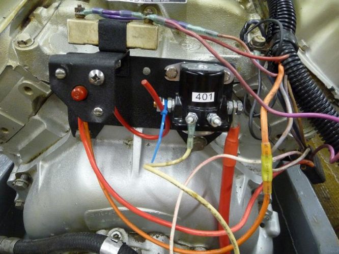 Well, why didn't you say so? It's really not intuitive at all. Here's a picture from the internet, that should give you an idea maybe . Ignore the "not too pretty" wiring and the different style relay. Your relay goes in the same spot though. |
Posted By: KENO
Date Posted: April-21-2021 at 6:43pm
|
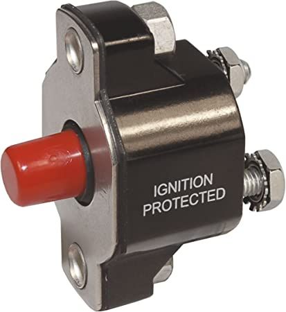
And here's one from CCF showing the breaker bracket more centered, then the plastic piece should be intuitive after that The Red breaker button fits in the hole in the plastic cover
 |
Posted By: Erikgundy98
Date Posted: April-21-2021 at 7:18pm
Thank you so much! This is exactly what I’ve been looking for, and I bet prior to the ranch somewhere hacked… I bet I would’ve been able to find that on my own. I just read through these posts, that appear to possibly have pictures with them, but don’t see very many pictures… And I don’t know the right language or vocabulary to search for some of these things. I really appreciate these pictures! |
Posted By: KENO
Date Posted: April-21-2021 at 8:08pm
|
Eric I'm just a search geek or search dork or fill in whatever word you want to..........or I go take my own pictures If you use your favorite search engine like say Google and type in "correctcraftfan starter relay" knowing that the relay bolts to the plate, when the results come up click on "images" and you get a bunch of photos, some pertinent, some not. In this case the picture I posted was found that way on the Mastercraft website since Google is so smart. You can type in correctcraftfan followed by whatever you're looking for and find a lot of stuff that way. You can also veer way off course, but you'll learn a lot along the way. In the case of the gone forever photos from CCF, sometimes you'll see them on a Google search on the images page. You can also type the name of the person like for example correctcraftfan keno distributor if you know the screen name of the guy whose post you're looking for It's a finely honed skill that I learned from a 13 year old PS........there are probably better ways, but this works pretty good for me
|
Posted By: Gary S
Date Posted: April-21-2021 at 9:05pm
I don't think there is any reason that you can't. The filter PCM uses in their FCC's is a 10 ------------- http://www.correctcraftfan.com/diaries/details.asp?ID=1711&sort=&pagenum=1&yrstart=1966&yrend=1970" rel="nofollow - 69 Mustang HM SS 95 Nautique Super Sport |
Posted By: Erikgundy98
Date Posted: April-25-2021 at 7:27pm
|
I upgraded the alternator to the 100 Amp alternator, with new cable from alternator to starter relay. Since the cable has a 100 amp fuse, I’ll bypass the 60a breaker with this cable. I was going to eliminate the 60a breaker, but the power (red wire) needs something to connect to (in the diagram it comes off the breaker). The terminals on the back of the breaker are too small for the large eye on the new cable anyway. I assume this is correct. Correction (if necessary) appreciated! :) |
Posted By: KENO
Date Posted: April-25-2021 at 7:57pm
|
Sounds OK to me. Big cable (of some not mentioned size" with 100 amp fuse going to the A terminal on the relay lets the alternator charge the battery at 100 amps if necessary and leaving the 60 amp breaker in place with the red wires attached will protect the wiring going up to the dash which isn't big enough for 100 amps. So.........what size is the new alternator output wire? And, is it safe to assume that you won the battle with the fuel pump?
|
Posted By: Erikgundy98
Date Posted: April-25-2021 at 8:15pm
|
Yep. Won the battle w/ fuel pump. :) https://www.nautiqueparts.com/product/fuse-link-circuit-breaker-to-starter-100-amp-fused-wire-pcm-gm-engines-from-2002-on-r153018a/ doesn’t list size. I don’t know the gage wire. But it’s bigger than the old one, and smaller than the ones coming from battery and going to starter. I just can’t believe the diagram that came with this wiring harness. The new wiring harness has white wires, yet I don’t know what the white connect to. Looking for white connections, If you look at the diagram it says “3” connects to white/red, but next to the image of the “3 wire”, it says white. https://drive.google.com/file/d/15SbXM1X_gZkJpnw50y_JOg1MINMcFnfl/view?usp=drivesdk Current fight is this wiring harness ;) At the rear of the engine, just off the plug, there are two groups of wires: approx 14ga red and 16ga purple wire, and a larger red (10ga maybe) and 16ga white connected to many more white of same ga. Assuming red and purple go to resistor; 10ga red goes to 60A breaker. But those white wires. Has anyone else installed this harness, on a ‘94 SN? https://drive.google.com/file/d/1THnamS_-nEIdq35MTxASzsNO5I2eC-Lv/view?usp=drivesdk I installed the resistor, but do I have to cut the ends of the purple and red to connect to the resistor? Can’t believe in their “kit” I would need to do this. Hmmm Thanks for the help. Erik |
Posted By: Erikgundy98
Date Posted: April-25-2021 at 8:48pm
| I’m wondering how many wires on this harness are not necessary, if you get rid of the throttle body.... |
Posted By: KENO
Date Posted: April-26-2021 at 5:48am
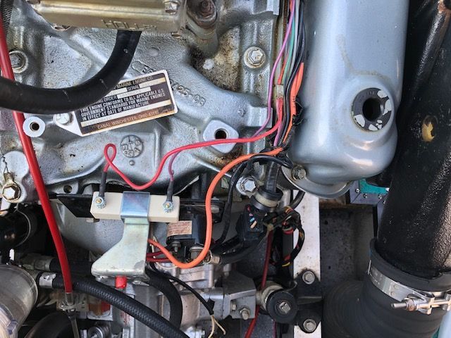
In your first linked picture where you ask "what is this"..........it's the neutral safety switch. On your PCM 40A transmission, it's at the top front and you'll have a white wire from your harness coming from pin 3 going to one terminal and another white from the other terminal to the "S" terminal on the start relay. The switch looks like this. It doesn't matter which terminal you hook which wire to. It's basically an open/closed switch, that's open when the transmission is not in neutral and when in neutral it's closed so that when you turn the key, power will be supplied through it to the "S" terminal.  The red and purple should hook to the resistor like you said. Some resistors have spade type terminals with a little hole in each spade for a small machine screw and nut to hold the wire to the resistor terminal, others use spade type connectors, so maye you have a little modifying of the ends of the wires to hook things up. The TRBenj diagram earlier in this thread is your best friend right now It shows red/yellow instead of white to the neutral safety switch. PCM used both colors over the years.I seem to think that he made his colorful diagram because the PCM was a "little" harder to follow and make sense of. Hang in there, you're making progress |
Posted By: Erikgundy98
Date Posted: May-02-2021 at 7:52pm
|
A few questions: This green wire, at wiring harness plug, I can’t find what it was connected to, and I can’t find it on the wiring diagram. https://drive.google.com/file/d/171BUZqmMYLa8awqvDwlBUiyBBMQXWK8a/view?usp=drivesdk Does it not connect to anything after this upgrade? Question 2- the ground for the carburetor choke. Is this little black wire, that came on the carb, is it now grounded to the carb, in turn grounding to the block? Or should I pull the small wire, and connect the 14ga ground wire here (in picture) to the choke in its place? I will have to change the connector, as this one on the harness is a male, and so is the choke. https://drive.google.com/file/d/16BAhkOzKTfLGfVO_2GOTRgk15ZieQpai/view?usp=drivesdk I also upgraded the alternator, so with it came a 6ga wire. Recommendations on where it connects to the block? And Nautique parts instructed me to connect the red eyelet of the alternator plug to the positive stud on the alternator. Seems very redundant to me. Anyone else get this advice? https://drive.google.com/file/d/1ZGMmLSQ4llR0s78QOIDjYSDJBTJT7euK/view?usp=drivesdk Thanks!! Erik |
Posted By: KENO
Date Posted: May-02-2021 at 8:32pm
|
Question 1 The green wire goes to the warning light on the dash for low oil pressure or high water temperature, but since the new harness has no connections for that, you can leave it disconnected or run wires to your oil pressure switch and coolant temp switch. Easiest is to leave it disconnected and tell yourself that real men use the gauges and don't need no stinkin' warning light Alternately, people have done things like wire the switches back to that Green wire to retain the warning light. If you want to do that, continue the green wire to each switch. Question 2 Read the thread in the link below, you can ground it either way (Second picture didn't work, need some kind of permission to view it.) http://www.correctcraftfan.com/forum/forum_posts.asp?TID=38633" rel="nofollow - link Question 3 I think I'd do what they say, it provides the voltage sensing signal to the alternator. |
Posted By: Erikgundy98
Date Posted: May-03-2021 at 8:58pm
|
So I think I’m done wiring. Thank you Keno (& others) for all your help. https://drive.google.com/file/d/1amC-ZWi_QdHQoKBMDuU0XjZKVNmD3EBs/view?usp=drivesdk I am now moving on to installing the replacement steering cable. But I really want to turn it over (engine) just to see if the wiring is all finished, good, & correct. Is it advisable to put the intake hose in water, even if just turning it over to check if all wiring is correct? Not going to set timing yet. But, to do so, I would install muffler to keep water out of the boat. I haven’t installed my muffler yet, as I like the room for accessing steering cable. I guess I’ll just do the cable and turn it over another night. Anything “burning” (or advisable) to do while I’m here without the muffler in? Boat has 1100 hrs. Transmission fluid is a nice red color, & is full. Not sure last time it was changed. Hesitating on “doing more” as I already bit off a lot. But I know, the last thing I want to do is burn up the tranny. Thanks again Erik |
Posted By: Gary S
Date Posted: May-03-2021 at 9:27pm
|
I vote for doing it now while the muffler is out you'll just have that much more room. If your only going to turn it over just remove the belt to the raw water pump ------------- http://www.correctcraftfan.com/diaries/details.asp?ID=1711&sort=&pagenum=1&yrstart=1966&yrend=1970" rel="nofollow - 69 Mustang HM SS 95 Nautique Super Sport |
Posted By: Erikgundy98
Date Posted: May-03-2021 at 9:50pm
|
Thanks Gary! I thought this past would be easy- but, spark plugs... from #1, are they going clockwise or counterclockwise? I have a LHR motor I don’t have an example to go from, and I can’t seem to find result in a search that will show me. I know the order for this is 13726548... but cc or ccw? Stupid question. Sorry guys. I’ll keep searching, but if someone finds it before me, thanks a lot!! |
Posted By: Jonny Quest
Date Posted: May-03-2021 at 10:35pm
|
Your SBF distributor runs counter-clockwise. ------------- Current 2003 Ski Nautique 206 Limited Previous 2001 Ski Nautique Open Bow 1994 Ski Nautique Open Bow Aqua skiing, ergo sum |
Posted By: Erikgundy98
Date Posted: May-03-2021 at 10:42pm
Thank you guys. |
Posted By: Jonny Quest
Date Posted: May-03-2021 at 10:58pm
|
Perhaps I should clarify...the rotor turns counter-clockwise. ------------- Current 2003 Ski Nautique 206 Limited Previous 2001 Ski Nautique Open Bow 1994 Ski Nautique Open Bow Aqua skiing, ergo sum |
Posted By: KENO
Date Posted: May-04-2021 at 6:06am
|
And here's the visual example for your normal rotation 351w  |
Posted By: Erikgundy98
Date Posted: May-04-2021 at 7:01pm
|
Somewhere I picked up the idea I need to gap spark plugs @ .35. That’s correct right? When I look at the owners manual for 1995 (I can’t find one for 1994, my year and model engine) I find .45. Do I go with this .35 due to the new set up? Or stick with what the ‘95 engine calls for for proper gap? |
Posted By: KENO
Date Posted: May-04-2021 at 7:39pm
|
You left out some zero's. You really mean .035 and .045 Either will work, but with your electronic Mallory .045 should be no problem at all.
|
Posted By: Erikgundy98
Date Posted: May-04-2021 at 7:43pm
|
Yes I did! Thanks! |
Posted By: Erikgundy98
Date Posted: May-16-2021 at 1:35am
|
Ok, all wired up. Bad fuel out, new fuel in. Got it primed, and... it’ll turn over, but won’t stay running once I let the key kick back to “on” from the start position. I’ve read somewhere someone had something backwards, and it started up. I’ve been over and over the diagram, and I don’t know what isn’t right. When key is on, (not start, but on) isn’t power supposed to be being sent to the coil and distributor? Unless the key is being held to “start”, there is no power at purple positive side of coil with key on. I could be wrong, but I thought the reason we don’t want to “leave the key on” in old systems like this (when the boat is not running) is due to the supply of power to these components when key is on. Again, I could be wrong. I will search for the thread where someone switched something... but can’t remember where I read it |
Posted By: 8122pbrainard
Date Posted: May-16-2021 at 5:36am
Correct. The first thing I'd check is the safety lanyard switch. ------------- /diaries/details.asp?ID=1622" rel="nofollow - 54 Atom /diaries/details.asp?ID=2179" rel="nofollow - 77 Tique 64 X55 Dunphy Keep it original, Pete < |
Posted By: KENO
Date Posted: May-16-2021 at 7:03am
|
It sounds like your engine starts with the key in Start but when you let the key go, it quits If you have a lanyard and it's unplugged, the engine will turn over but not start if things are wired per the diagram, since the lanyard in your case kills power to the coil no matter what position the key is in unless you have some "really creative" wiring
.Look at the "R" terminal on the back of your key switch and check that you have about 12 volts there with the key in Run. Verify that the purple wire is connected to that terminal while you're at it. If you don't have 12 volts at the "R" terminal, the switch is bad Start with that check to begin figuring this out. |
Posted By: Erikgundy98
Date Posted: May-16-2021 at 12:28pm
|
12V at purple wire on back of ignition when key in “run” (on) position. Going to double check all connections, that they are in correct places. Other thoughts? I have continuity through white wires on top of transmission, have verified breaker has continuity through it, and that the resistor has continuity through it. I since there is power in the “run” position at ignition, I should then have power at purple in back.... this is what I am checking now.... |
Posted By: Erikgundy98
Date Posted: May-16-2021 at 1:24pm
|
With ignition in on position, have power to the safety lanyard switch. But, even with power to it (12V) to one side, with clip in, no power on opposite (out) post. I assume with the clip in, it allows power to continue to ignition. But, with clip in or not, no power to out side of switch. Off to store to replace switch https://drive.google.com/file/d/1t0MHXKfbQx7aORdmjjIPzcHwW22fbXsN/view?usp=drivesdk So, the switch was bad! Engine purrs. Time to time it https://drive.google.com/file/d/1TdXa-RA2IoRO1Qkux5VBYSnC779CMLTp/view?usp=drivesdk |
Posted By: 8122pbrainard
Date Posted: May-16-2021 at 1:50pm
|
Erik, Good troubleshooting. I think you found the problem. https://drive.google.com/file/d/1t0MHXKfbQx7aORdmjjIPzcHwW22fbXsN/view" rel="nofollow - 64287912932__130A8D16-2C0A-4F71-8984-33B14CAF392A.MOV - Google Drive ------------- /diaries/details.asp?ID=1622" rel="nofollow - 54 Atom /diaries/details.asp?ID=2179" rel="nofollow - 77 Tique 64 X55 Dunphy Keep it original, Pete < |
Posted By: KENO
Date Posted: May-16-2021 at 2:46pm
So does the sentence above mean that the engine actually ran with the key in Start or did it just turn over but not run. If it actually ran, I'd like to see where and how the switch is wired into the circuit And will ya look at that, you took a bunch of parts that came with little or no instructions and made it through the installation with a little CCF help.
|
Posted By: Erikgundy98
Date Posted: May-16-2021 at 3:49pm
|
You’re serious!!! I did! It was all your guys help that got me through! Yes, the switch has two spade connectors on it, both connected to purple wires, and back at the starter relay and resistor, I had no power to purple. So after your (both of you) advice to check ignition switch purple wire for 12V (which I verified it had) I figured these purple wires needed to feed the relay. One hot, one not. Pulled switch, tested continuity, it didn’t have continuity when lanyard was correctly and securely installed, so I used a jumper to bypass switch, and it started and stayed running! Timing set. NautiqueParts says 5 degrees atdc, so I set it there (with electronic timing light), set idle to 650, and it starts with one bump of the key, and purrs amazing!! Thank you for all your help!!! I wouldn’t have done it without you guys! Couldn’t have done it alone. Now on to see why the blower button doesn’t stay in/on ;) |
Posted By: KENO
Date Posted: May-16-2021 at 5:11pm
You sure you don't mean 5 degrees BTDC or even 10 gegrees BTDC?
|
Posted By: Erikgundy98
Date Posted: May-16-2021 at 6:49pm
|
Maybe. The nautique parts guy (Townsend) who was helping answer my questions said first, “8-10 over top dead center.” Is this “over” meaning ‘before’? Where the white marks on my harmonic balancer used to be (still are, but were for old system) a mark at 10 and another mark at 18, I did time it at 5, to the same side (must be Before, as you say)... But when I read the engine specs on the top of my engine, “static” (is that with engine off?) says 8-10, and 18 degrees BTDC @700rpm w/ prop engaged. I set it to 5, with engine idling around 1000rpm, then set idle to 700, and it still purrs w timing set at 5 (must be BTDC). But, should I time this with prop engaged, like the Sticker says? To what do I time it then? My prop doesnt spin very easily, In fact I really have to put muscle behind it to turn it, and transmission is in N. Is this normal? I can turn it, but it doesn’t spin easily. But it’s been 2 years since running. I don’t see a zerk fitting on prop like I see on rudder |
Posted By: KENO
Date Posted: May-16-2021 at 7:00pm
|
Them southern boys talk funny, but i'd imagine he meant Before. Ignore the sticker, it pertains to the old system that you took off the engine. You can time it in neutral with no issues. You should have 10 as mentioned and if you rev it up to 4000 rpm, you should top out at somewhere in the 30 to 35 BTDC range depending on the advance weights and springs in the new distributor.. If your cutlass bearing is dry, it'll take more effort to turn the prop, spray some water on the strut to get the bearing wet and see how it turns. You could have alignment issues too causing the hard turning.
|
Posted By: Erikgundy98
Date Posted: May-16-2021 at 7:57pm
The “spray some water on the strut”... where is the strut? Thanks! So happy with the engine progress. My son and I have been doing it together. He’s 10. All new language to him, “bilge pump”, “bilge” (then he makes the connection “ oh, the bilge pump is in the bilge!” - yep!) So, thank you for helping us through this fun process we’ve had together. |
Posted By: 8122pbrainard
Date Posted: May-16-2021 at 8:16pm
 ------------- /diaries/details.asp?ID=1622" rel="nofollow - 54 Atom /diaries/details.asp?ID=2179" rel="nofollow - 77 Tique 64 X55 Dunphy Keep it original, Pete < |
Posted By: Gary S
Date Posted: May-17-2021 at 12:24am
Kinda though this was funny- There is a guy on FB who is a ASE tech who can't get his 94 with a carb to run right. He wants to go back to it's original induction. It has EFI decals on the boat so he figures it had to have fuel injection. Can't get a carb to run right but being a ASE tech I'll bet he'll have that Pro Tec up and running in no time Maybe Erik can sell off his old set  ------------- http://www.correctcraftfan.com/diaries/details.asp?ID=1711&sort=&pagenum=1&yrstart=1966&yrend=1970" rel="nofollow - 69 Mustang HM SS 95 Nautique Super Sport |
Posted By: Erikgundy98
Date Posted: May-17-2021 at 1:21am
|
I will, I don’t need it. I don’t want to throw it away. I feel bad for the guy who posted on FB, (https://drive.google.com/file/d/13sK8-aZ52mQ_58uIdH-KFy7VEqbE8iwp/view?usp=drivesdk) $8500 into his rehab, & didn’t check if engine was seized. That was the first thing I checked, and I was scared when I did (but it was good, and with plugs in, it was hard to turn over). I was still scared not being able to do a good compression test (but I inferred difficult turning over (by hand) was due to good compression) before handing NP a huge chunk of change for all the parts I swapped. But it purrs now. I’ve got a few leaks (impeller slow-dripping ( https://drive.google.com/file/d/1StiP0YH5Ey6p0EsBUVCt6k6BVAcNa_Xi/view?usp=drivesdk), exhaust riser is leaking at new small gasket (it’s tight, but under old gasket it was pitted pretty bad, and I know I have work to do there), & there’s water coming toward the battery from the heater core. Bet my brother didnt drain that when he “winterized it” and then left it outside. Oh well, just more to fix ;) Anyone have success with ATV red gasket maker under the gasket? I think I did that on my last boat 15 years ago at the advice from the previous owner, and it held from what I remember. I know the correct thing to do would be to have it machined down flat. Anyone add JBWeld, and then grind flat? That’s done on Vanagon heads a lot (which is my other backyard mechanic experience). Thanks for advice! I’ll be looking and researching threads now ;) |
Posted By: KENO
Date Posted: May-17-2021 at 6:29pm
|
You've already mentioned the best solution, but depending on your budget the other 2 may work for you. If you're comfortable with it from your previous BYH experience, then it's your choice
If the pitting is bad enough and widespread enough in that area, you might have water leaking into the exhaust side of the engine along with the external leak. That'll make more issues. |
Posted By: Erikgundy98
Date Posted: May-17-2021 at 7:55pm
|
My worry is getting the exhaust manifold bolts loose. They look like they’ve never been removed before. Dang it. Ok, I see how much worse it could be, if I am getting water in the exhaust. Damn! I’m so bummed as I want to be on water on Memorial Day! |
Posted By: KENO
Date Posted: May-18-2021 at 5:29am
|
Don't get bummed yet Not knowing what your surfaces look like, the internal leak is a possibility, not a guarantee If you were to get in some run time first, then pull the plugs to check for any water/moisture in the cylinders and check the oil for water, you'll know if you have an internal leak. I'd probably get in some run time on Memorial Day just to check for any running issues of any kind with all the work that you've done..
|
Posted By: Erikgundy98
Date Posted: May-27-2021 at 8:38pm
|
Thanks for the advice on getting on the water. Yesterday I took it out on Lacamas Lake (Camas, WA) to do a test run. found a good sized leak on the electronic thingy thru-hull (next to the drain plug). I have been searching the manual, and this forum, for details on what this is. Its a grey plastic, and on the bottom there is a little spinning wheel. What is this thing called? It is leaking. Its leaking along the gasket. What is it? Can I just tighten the large nut, or is it advised to apply calk or something on the outside of it? I think it might be part of the Perfect Pass... I have no idea! Thanks Erik
|
Posted By: DVskier
Date Posted: May-27-2021 at 8:53pm
| Erik, That is the paddle wheel for the Perfect Pass speed control. |
Posted By: KENO
Date Posted: May-27-2021 at 8:55pm
|
I think you really do have an idea Here's a link to a PP manual http://www.perfectpass.com/sites/all/themes/perfectpass%20-%20Copy/images/wakeboardpro2005.pdf" rel="nofollow - link It may or may not be exactly the same version but on page 13 it talks about the paddle wheel installation. I'd take it out and reseal it from below like the manual describes. It mentions GE silicone sealant. Some people break out in hives whenever silicone gets mentioned and they might recommend 3M4200 or maybe Loctite PL Marine sealant. They're both plenty strong but easier to remove than something like 3M 5200 You can find the Loctite stuff at Home depot in the paint department pretty easily Did you get to run it for a while or was the leak too big?
|
Posted By: Erikgundy98
Date Posted: May-27-2021 at 9:49pm
|
Funny story. You want it? So a friend of mine has a boat. I ask him to meet me at the lake so if I need a tow in, he’s there. He does. But day before we meet, he buys a new (2019) 12 passenger Yamaha double jet boat (twin engines). It’s big. I meet him out on lake. I am nervous, first time in this boat on the water. I find this leak (mentioned above, thanks by the way!!), and it takes 30 seconds of cranking to get it to start (gotta get that figured out), but when it starts, it purrs. We putt out to middle of the lake and meet my friend. He gets his going a bit. I do too. I’m probably 2500 rpm max. I have a flat spot. With throttle sticking in one spot, it revs back and forth, like I’m feathering it (but I’m not). But then he punches his boat. He takes off. I do too. And I leave him in the dust!!! I mean, he was trying to catch me, which kept me with the throttle goosed, and just letting it go. 4,000 rpm is what I read, and he said he was going 45 and couldn’t catch me. So it moves! Wide open it moves. But that flat spot.... hope I don’t have a skier (kid) skiing slow, and have that problem. No problem at all at idle. At 1000-2000 rpm, no prob. But right around 2500, it revs up and down. Thoughts? Thanks for the link! My buddy, (who just dropped $60K on a Yamaha, which I know is nothing now a days) his wife was not impressed with their new purchases’ ability to catch us ;) ha! |
Posted By: KENO
Date Posted: May-28-2021 at 6:34am
|
What's your cold starting routine? What's the choke position when the engine is cold?
|
Posted By: Erikgundy98
Date Posted: May-28-2021 at 8:46am
I first tried to just turn the key without giving it gas at all. That didn’t work. So I then cranked with giving it throttle (first about 1/8 throttle, which wasn’t enough I thought (as it wasn’t catching, wasn’t sounding like it was even close) so I gave it more, giving it throttle until it hit the neutral button), and still nothing, so I kept cranking it, as I wondered if the fuel had just left the fuel line and been sucked back into the tank. I thought maybe my anti syphon valve wasn’t working. Then it finally caught, and purred. I don’t know where the choke position you speak of, is. |
Posted By: 8122pbrainard
Date Posted: May-28-2021 at 9:25am
Holley 4 barrel choke: (ignore fast idle cam proceedure) https://forums.holley.com/entry.php?439-How-To-Adjust-The-Electric-Choke-On-A-Holley-Four-Barrel-Carburetor#:~:text=How%20To%20Adjust%20The%20Electric%20Choke%20On%20A,time%20until%20the%20choke%20performs%20properly.%20More%20items" rel="nofollow - How To Adjust The Electric Choke On A Holley Four-Barrel Carburetor - Blogs - Holley Performance Products Forums Bench test choke (engine not running): https://www.bing.com/videos/search?q=how+to+adjust+holley+choke&qpvt=how+to+adjust+holley+choke&view=detail&mid=F8DC6FD7BB76E9C81EF1F8DC6FD7BB76E9C81EF1&&FORM=VRDGAR&ru=%2Fvideos%2Fsearch%3Fq%3Dhow%2Bto%2Badjust%2Bholley%2Bchoke%26qpvt%3Dhow%2Bto%2Badjust%2Bholley%2Bchoke%26FORM%3DVDRE" rel="nofollow - 19. Holley carb rebuild (electric choke bench test) - Bing video Note when cold, the choke butterfly is just slightly open.
------------- /diaries/details.asp?ID=1622" rel="nofollow - 54 Atom /diaries/details.asp?ID=2179" rel="nofollow - 77 Tique 64 X55 Dunphy Keep it original, Pete < |
Posted By: KENO
Date Posted: May-28-2021 at 12:34pm
|
Erik My ultra keen powers of perception tell me that you're young enough that you missed one of those teenage rites of passage into manhood............ pumping the throttle You probably never had a car with a carburetor, but the typical routine was to pump the gas pedal a couple of times right before you turned the key. It did a couple of things, first it set the choke and the high idle cam and it also shot a couple squirts of gas down the carburetor from the accelerator pump. Being a boat, with a marine Holley, the fast idle linkages aren't all there and connected and don't work. But those shots of gas help make it start quickly. None or not enough makes for a tough start, too much makes for a flooded engine and a tough start. You could have 12 people tell you their starting routine and they'd all be somewhat different, but if your choke seems OK from the videos above and you pump the throttle a couple of times and with it in neutral, you turn the key it should fire right up and you then play "human fast idle cam" and let it warm up for a minute or so at around 1200 to 1500 rpm, the electric choke will be open or most of the way open and you can bring it back to idle, then go happily on your way. Some will have the throttle cracked a little while turning the key, others will leave it at idle speed, some pump with the neutral button pressed in so they can give it some good pumps, some pull it out but pump in Reverse, some lpull it out and pump till it hits the button, some people spend a lot of time dialing their choke into the Holley spec while some just disable the choke in the fully open position. Like i said, you could get lots of opinions and variety so do whatever works for you. Carburetors are like women, they can be a little..........well you know I'd start by a quick check of the choke operation (which should be OK as shipped) and pump it a couple of times and see what happens then you can come up with your own routine..
|
Posted By: Erikgundy98
Date Posted: May-28-2021 at 4:29pm
|
Ha! Cause I didn’t miss that right of passage, I just didn’t know what was happening when I used to pump my 1979 rabbit, or might 1970 Carmen Ghia gas pedal before I started. OK, so the rabbit was fuel injected :-) but, when I did get my first carbureted car and second and third, and I would use the exact thing you described, I didn’t actually know what was happening. So your explanation, and now bringing all of that back, I appreciate your explanation! When I rebuilt my first carburetor, I learned about the functions of everything you just described. But, I guess I just didn’t realize that this holly carburetor, although 2 to 3 times larger than my old pict-3, operates much the same. I had no idea how similar this holly carburetor, and my little tiny carburetor on my old V dubs, are. At least, as you explain the functions of this carburetor, I see all the parallels. Thanks for your advice. So now, the perfect pass has been resealed, but… In removing that, I noticed new red tranny fluid in the bilge. Awesome. (Not awesome). I inspected the lines to and from the cooler, and couldn’t find any leaks anywhere… Until I wiped my hand on the bottom point of the transmission, and it was wet, red. Ugh. Any chance my seal might have just been dry, and… It’s going to seal up on its own? I will be picking up an extra bottle for this weekend. Dang it |
Posted By: KENO
Date Posted: May-28-2021 at 7:51pm
|
There's a chance it might seal up on it's own. About as much as seeing Bigfoot and the Loch Ness monster playing together If the leak isn't very bad, you could join the "if it don't slip, let it drip" club for a while, so you can get all your bugs worked out, then get through the season and get it fixed or tear into it yourself. Oil absorbent towels/socks can help keep things like your lake from getting an oil sheen from your bilge pump. As far as your 2500 rpm stumble, I'm still doing some thinking on that. PS buy yourself one of the many Holley books that are available, it'll be real handy
|
Posted By: KENO
Date Posted: May-29-2021 at 9:26am
|
Eric Here in the link below (on page 19 of the printed manual) is how PCM tells you to start their carbureted engines, it sounds suspiciously pretty much like what was described earlier http://www.correctcraftfan.com/downloads/PCM_Owners_Manual_Ford_and_Chevy.pdf" rel="nofollow - link
|
Posted By: Erikgundy98
Date Posted: May-29-2021 at 10:06am
| Could the perfect pass be doing the stumbling? There is another electronic piece under the copilot seat, that was just hanging (not actually fixed to a rigid location in the boat), and honestly I don’t know which way to sim it. It says to aim towards the bow if using north facing magnets, and sim to the stern if using south facing magnets. I don’t know what this means, so I don’t know which direction to aim it. |
Posted By: Erikgundy98
Date Posted: May-30-2021 at 2:54am
|
So, no stumble when Perfect Pass is turned “Off.” I guess I’ll figure out how that thing works later. For now, hoping the transmission stops leaking, or it’s gonna be a short summer. Does the “ignition” button have to be depressed to run the “automatics bilge pump”? Assuming there is no power to anything “ignition” related, aka coil, etc when the key is not turned “on”. Is that correct? Fun day fishing and boating. Thanks for all the help. I couldn’t have had today with my family without your help! |
Posted By: KENO
Date Posted: May-30-2021 at 5:53am
|
Well, you've come a long way from a pile of expensive parts with no decent instructions, sounds like the boat runs good and no labor charges were involved. The auto bilge pump should be wired so it'll run with the ignition breaker OFF. And like you said, you should have no power to anything ignition related with the key in OFF. Now it's time for "the talk" No, no nothing to do with those teenage years, just your transmission. I guess it's bad enough that you won't be living with it for a while based on your last comment about a short summer. If you can figure out if it's leaking from the front or back, doing a seal on either end isn't too bad. Assuming it's a PCM 40A, somebody here just did the rear seal with it still in the boat but it has to come out for the front seal. You can do some searching about transmission removal, seal replacement etc here on CCF. You can also read about damper plate replacement while the transmission is out and decide if you want to do that too. Keep in mind that your PCM 40A takes it's own "special" damper in the 200 dollar or so range. Here's a link to a recent rear seal thread complete with a phone number for Joe at FFI marine who would have parts and probably some free advice too. http://www.correctcraftfan.com/forum/forum_posts.asp?TID=49789&title=rear-transmission-leak-40a" rel="nofollow - link Meanwhile I'm gone for the next 4 or 5 days so enjoy the rest of the weekend, do some reading and you'll be able to get through a seal job.
|