 Boats For Sale:


1969 Mustang Stringer Rebuild |
Post Reply 
|
Page <1234 15> |
| Author | |
TX Wind 
Senior Member 

Joined: March-29-2011 Location: near Dallas Status: Offline Points: 335 |
 Post Options Post Options
") Thanks(0) Thanks(0)
 Quote Reply Quote Reply
 Posted: July-01-2011 at 1:16pm Posted: July-01-2011 at 1:16pm |
|
Wow you've got a lot to do David but it's looking good. Tomorrow morning when you're finishing up, grab a quick shower to scrub the grime off and let your wife hook the trailer up while you catch a cat nap LOL.
|
|
 |
|
|
vondy
Platinum Member 

Joined: November-29-2007 Location: Dallas, Texas Status: Offline Points: 1116 |
Post Options
Thanks(0)
Quote Reply
Posted: July-01-2011 at 12:43pm |
|
Pete I planned on painting them but first things first. Got to get this baby together if I'm going to take her on our trip first thing tomorrow morning. Man I'm cutting it close. Probably rebuilding or replacing the short block next year so I'll paint them then.
Left to do.... 1. Flywheel 2. Dampener 3. Bellhousing 4. Transmission 5. Line everything up so I can cut my exhaust hose to the proper size. 6. Figure out my shaft log hose length then put it in place. 7. Instal prop, already lapped 8. Connect remaining wires and hoses 9. Instal gas tank 10. Build side pannels 11. See if she runs |
|
|
|
|
8122pbrainard
Grand Poobah 

Joined: September-14-2006 Location: Three Lakes Wi. Status: Offline Points: 41045 |
Post Options
Thanks(0)
Quote Reply
Posted: July-01-2011 at 11:55am |
|
David,
You didn't paint your wedges!! 
Go flap free. You will never get water back to the manifolds with those H/M goose neck risers. |
|
|
|
|
vondy
Platinum Member
Joined: November-29-2007 Location: Dallas, Texas Status: Offline Points: 1116 |
Post Options
Thanks(0)
Quote Reply
Posted: July-01-2011 at 11:45am |
|
Never can get quite as far as I'd like to in the time I have. This morning I started putting the engine in. Installed the flywheel then moved to the dampener. Sheared off one of the dampener bolts around 20 ft lbs. Don't know if that was too much torque or if the bolt was just too old. I'll pick up 3 new grade 8 ones at the hardware store.
When the engine tilted back, oil came out of the flywheel holes. Oops. Cleaned up easy enough. I know to seal the threads when installing but what is this extra hole for? I assume it's not open to the crank area? 


Debating on keeping these babies free of flaps.... 
|
|
|
|
|
vondy
Platinum Member
Joined: November-29-2007 Location: Dallas, Texas Status: Offline Points: 1116 |
Post Options
Thanks(0)
Quote Reply
Posted: June-30-2011 at 7:51pm |
|
thanks Pete!
|
|
|
|
|
8122pbrainard
Grand Poobah
Joined: September-14-2006 Location: Three Lakes Wi. Status: Offline Points: 41045 |
Post Options
Thanks(0)
Quote Reply
Posted: June-30-2011 at 7:02pm |
|
David,
No, it shouldn't hurt it. The ampmeter has a solid conductor post to post carrying the current. Then there's windings around it that create the magnetic field moving the needle. With a good battery that's not run down, I'd be surprised to see it hit the 40 amps. |
|
|
|
|
vondy
Platinum Member
Joined: November-29-2007 Location: Dallas, Texas Status: Offline Points: 1116 |
Post Options
Thanks(0)
Quote Reply
Posted: June-30-2011 at 6:12pm |
|
Pete we are lucky to have you here.

So pinging it out won't "fry" anything? I'm trying to avoid breaking anything by fixing it. |
|
|
|
|
8122pbrainard
Grand Poobah
Joined: September-14-2006 Location: Three Lakes Wi. Status: Offline Points: 41045 |
Post Options
Thanks(0)
Quote Reply
Posted: June-30-2011 at 6:05pm |
|
David,
Alternators never put out their "rated" ouput. The output of any alternator really depends on the condition of the battery and of course the other small loads. If your battery is run down, you may peg the gauge but only for a very short time. Yes on the ignition switch. Same "bat" term in and out with the heavy wire. |
|
|
|
|
vondy
Platinum Member
Joined: November-29-2007 Location: Dallas, Texas Status: Offline Points: 1116 |
Post Options
Thanks(0)
Quote Reply
Posted: June-30-2011 at 5:58pm |
|
Man..... OK so in one post and out the other on the amp gauge. Same post in and out on the ignition BAT. Right?
About what should my gauge be reading if everything is working correctly? I have no radio so at most the ignition, blower, bilge pump, lights.... Come to think of it, I'm not sure what the gauge goes up to. Probably not 105 amps huh? |
|
|
|
|
8122pbrainard
Grand Poobah
Joined: September-14-2006 Location: Three Lakes Wi. Status: Offline Points: 41045 |
Post Options
Thanks(0)
Quote Reply
Posted: June-30-2011 at 5:41pm |
|
No on the ampgauge. Go back to your original drawing - In one post and out the other. If they are backwards, the ampgauge will just read backwards.
|
|
|
|
|
vondy
Platinum Member
Joined: November-29-2007 Location: Dallas, Texas Status: Offline Points: 1116 |
Post Options
Thanks(0)
Quote Reply
Posted: June-30-2011 at 5:35pm |
|
Understood. Basically instead of connecting directly to the battery it goes to the battery via the same post on the solenoid that the battery cable is connected too.
So it's a loop, touching the gauge and ignition. It does not go in one post and out another, same post in and out, right? 
|
|
|
|
|
8122pbrainard
Grand Poobah
Joined: September-14-2006 Location: Three Lakes Wi. Status: Offline Points: 41045 |
Post Options
Thanks(0)
Quote Reply
Posted: June-30-2011 at 5:27pm |
Yes but you want it connected at the solenoid to the stud where the + battery cable is connected. Don't mix it up with the small wire that energized the solenoid coil. That should be the white wire. |
|
|
|
|
vondy
Platinum Member
Joined: November-29-2007 Location: Dallas, Texas Status: Offline Points: 1116 |
Post Options
Thanks(0)
Quote Reply
Posted: June-30-2011 at 4:59pm |
|
I believe a 1/4 of my wires are not original so who knows if the colors match. Probably why I'm having trouble here.
So from amp to BAT on key. Then do I go from BAT to Solenoid? |
|
|
|
|
8122pbrainard
Grand Poobah
Joined: September-14-2006 Location: Three Lakes Wi. Status: Offline Points: 41045 |
Post Options
Thanks(0)
Quote Reply
Posted: June-30-2011 at 4:50pm |
|
David,
The red from the amp goes to the red on the key switch which is the "Batt" terminal. Leave all the rest of the wires on the key switch the same. The 3rd terminal on the amp is for lighting but should be the switched hot. The case would be the ground. Do check it out since some gauges are set up slightly different. BTW, the way you have it drawn, you would have power to the ignition all the time. Think of the key switch this way - the "bat" terminal in "IN" and all the rest are switched "OUTS". |
|
|
|
|
vondy
Platinum Member
Joined: November-29-2007 Location: Dallas, Texas Status: Offline Points: 1116 |
Post Options
Thanks(0)
Quote Reply
Posted: June-30-2011 at 4:30pm |
|
Thanks Pete, sometimes these diagrams blow my mind so see if I got this right.
I traced in red what I think I am supposed to do. The red represents my new 6 gauge wire. Alt to amp gauge. There are 3 post on the gauge, one I believe is ground. For the other two post I would connect my alt wire in and out the other to the key switch. At the key switch I could connect to the IGN post. Then would leave out of the BAT terminal back to the battery side of the solenoid. Missing anything? 
|
|
|
|
|
8122pbrainard
Grand Poobah
Joined: September-14-2006 Location: Three Lakes Wi. Status: Offline Points: 41045 |
Post Options
Thanks(0)
Quote Reply
Posted: June-30-2011 at 3:36pm |
|
David,
Take a look at this wiring diagram. Maybe it will give you a better idea rather than me trying to put it in words. But yes, aternator to te ampmeter, ampmeter to the key switch and then the key switch to accesories,ignition system and back to the start relay (solinoid) to charge the battery. It goes to the key switch so the ampmeter will indicate the total load on the charging/battery system. Keep in mind the wire gauge to the ampmeter and back to the relay neds to be rated for the alternator output. 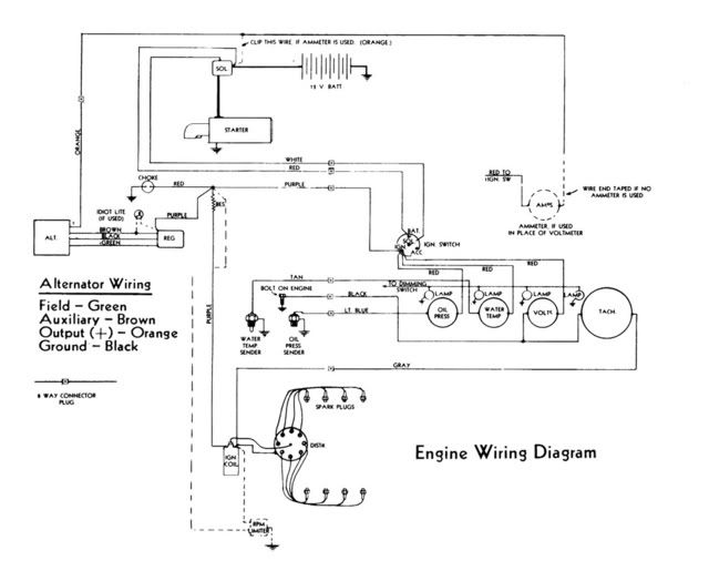
The 3rd post on the ampmeter is for the internal lighting. The case is the ground for the light. |
|
|
|
|
vondy
Platinum Member
Joined: November-29-2007 Location: Dallas, Texas Status: Offline Points: 1116 |
Post Options
Thanks(0)
Quote Reply
Posted: June-30-2011 at 2:28pm |
|
The more I look at this the more I wonder why it would need to go to the key? Wouldn't I just need to run from the alt to the amp meter to the battery?
|
|
|
|
|
vondy
Platinum Member
Joined: November-29-2007 Location: Dallas, Texas Status: Offline Points: 1116 |
Post Options
Thanks(0)
Quote Reply
Posted: June-30-2011 at 12:51pm |
|
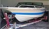
Well most everything is in and done besides the engine. Still have to hook up the prop, various wires, put the gas tank in, connect the exhaust, and other little things here-and-there.
Pete I need some help on this alternator wiring. I know we discussed but want to make sure I get it right so I don't blow anything up. You say to run my single wire from the alternator to the amp gauge. What post would I want to hook it up to on the amp gauge? I believe there are 3. Then you say from there go to the key switch. Again, what post? From there it runs back to the starter solenoid. I believe here it should connect to the post the battery connects too. It also appears there is a smaller post on the alternator, don't know if it's a ground wire or something? Almost there guys! Will drop the engine in tonight and pray she fits. Then pray she starts! Then pray she floats! |
|
|
|
|
vondy
Platinum Member
Joined: November-29-2007 Location: Dallas, Texas Status: Offline Points: 1116 |
Post Options
Thanks(0)
Quote Reply
Posted: June-28-2011 at 12:59pm |
|
Thanks for the comments everyone.
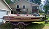
All my through hull-fittings are now in place. I'm planning on gluing the vinyl down tonight and dropping the engine in tomorrow. I'll run all the wires, cables and hoses before the engine goes in. If she runs,  , then I'll put the seats, etc in and hopefully be ready to go. , then I'll put the seats, etc in and hopefully be ready to go.
I will say, there is not one single easy thing on this project. Like this morning, I tried to get my new 1.5" hose onto the stuffing box. I don't see how it's possible. I heated it and could get it about half way then it cooled, shrunk, and slid off. I don't understand why the stuffing box and log are two different sizes. Was someone drunk when they designed that? I could go on for hours... but I won't. Just ready to be done. And hopefully reap the benefits of my hard work. |
|
|
|
|
MAN - GA
Senior Member

Joined: July-09-2009 Location: Cumming, GA Status: Offline Points: 298 |
Post Options
Thanks(0)
Quote Reply
Posted: June-28-2011 at 11:40am |
|
David,
Nice work and the motor looks great - I know this is a very minor comment in your overall progress, but is a little easier to do this now than after you get all the belts, cooler, etc. put back on the front of the engine. I see you put timing tape on the damper and I had done this as well when I recently replaced my timing chain and in the humidity under the motor cover it lasted one trip to the lake. From my experience you might want to use a paint marker to identify the degrees adjacent to the timing tape now before bolting all the appurtenances back up. Great job I will probably have to do this project sooner or later with my 75 Mustang |
|
|
|
|
8122pbrainard
Grand Poobah
Joined: September-14-2006 Location: Three Lakes Wi. Status: Offline Points: 41045 |
Post Options
Thanks(0)
Quote Reply
Posted: June-28-2011 at 9:21am |
|
Just the 5200.
|
|
|
|
|
Gary S
Grand Poobah

Joined: November-30-2006 Location: Illinois Status: Offline Points: 14096 |
Post Options
Thanks(0)
Quote Reply
Posted: June-27-2011 at 10:54pm |
|
Exactily how mine were done too.
|
|
|
|
|
connorssons
Platinum Member
Joined: January-17-2009 Location: Michigan Status: Offline Points: 1414 |
Post Options
Thanks(0)
Quote Reply
Posted: June-27-2011 at 10:50pm |
|
5200 both sides and in middle
|
|
|
|
|
connorssons
Platinum Member
Joined: January-17-2009 Location: Michigan Status: Offline Points: 1414 |
Post Options
Thanks(0)
Quote Reply
Posted: June-27-2011 at 10:48pm |
|
Hay Vond! looks super, you have been kicking aassssss! good luck on the maiden voyage

|
|
|
|
|
vondy
Platinum Member
Joined: November-29-2007 Location: Dallas, Texas Status: Offline Points: 1116 |
Post Options
Thanks(0)
Quote Reply
Posted: June-27-2011 at 10:47pm |
|
All I have are short stainless pipes that go through the wood supports and hull. There is a trim ring on the outside. Originally there was a fiberglass "shroud" that surrounded the pipe. I believe it was covered by the hose. Guess water could not get in that way.
Should I through any thickened epoxy around it or just hit it hard with the 5200? Here is kind of what it looked like. I had already ground some of it away. 
Here is a shot of how it goes together. 
|
|
|
|
|
Gary S
Grand Poobah
Joined: November-30-2006 Location: Illinois Status: Offline Points: 14096 |
Post Options
Thanks(0)
Quote Reply
Posted: June-27-2011 at 10:39pm |
If he's keeping it original,he'd have a fiberglass pan  ---- ----
I think it looks great David,your engine turned out nice too. |
|
|
|
|
8122pbrainard
Grand Poobah
Joined: September-14-2006 Location: Three Lakes Wi. Status: Offline Points: 41045 |
Post Options
Thanks(0)
Quote Reply
Posted: June-27-2011 at 9:52pm |
|
David,
You have the original design of exhaust flange. They were simply a flange and the copper exhaust tubing went though them. On the inside of the flange is a chamfer that accepted the rope packing. When the flange was tightened down to the transom, the packing would compress down on the tubing. Yes, glop it up with the 5200! |
|
|
|
|
DrCC
Grand Poobah

Joined: April-12-2004 Location: at home Status: Offline Points: 2890 |
Post Options
Thanks(0)
Quote Reply
Posted: June-27-2011 at 9:34pm |
|
Yes, I smear a thin layer in the hole with a healthy bead on the tube.
Cleans up alot better with mineral spirits than it does with acetone or lacquer thinner. |
|
|
|
|
vondy
Platinum Member
Joined: November-29-2007 Location: Dallas, Texas Status: Offline Points: 1116 |
Post Options
Thanks(0)
Quote Reply
Posted: June-27-2011 at 9:21pm |
|
There was some type of rope packing around my exhaust pipes when I removed them. Will the 5200 be enough to seal these off? It will be a tight fit already.
|
|
|
|
|
Keeganino
Grand Poobah

Joined: October-27-2009 Location: North Carolina Status: Offline Points: 2063 |
Post Options
Thanks(0)
Quote Reply
Posted: June-27-2011 at 3:17pm |
|
When my red carpet is done I hope to switch to the nautolex flooring too. I like the look of the red but it shows every little speck and is a chore to keep it looking clean. I am curious to see how much it takes to cover the floor and walls. Pretty sure the carpet I got was 6' wide and 15' long and I only ended up with 1 seam on the SB wall.
|
|
|
"working on these old boats may not be cost effective but as it shows its what it brings into your life that matters" -Roger
1973 Skier |
|
|
|
|
Post Reply
|
Page <1234 15> |
 Tweet
Tweet
|
| Forum Jump | Forum Permissions You cannot post new topics in this forum You cannot reply to topics in this forum You cannot delete your posts in this forum You cannot edit your posts in this forum You cannot create polls in this forum You cannot vote in polls in this forum |


 Topic Options
 vondy wrote: