Ammeter/alternator/breaker confusion
Printed From: CorrectCraftFan.com
Category: Repairs and Maintenance
Forum Name: Boat Maintenance
Forum Discription: Discuss maintenance of your Correct Craft
URL: http://www.CorrectCraftFan.com/forum/forum_posts.asp?TID=51007
Printed Date: April-27-2024 at 7:34pm
Topic: Ammeter/alternator/breaker confusion
Posted By: NeilMcG
Subject: Ammeter/alternator/breaker confusion
Date Posted: December-20-2022 at 12:15am
Phase II of the '78 SN restoration is underway and as the engine is out, this is a good time for a re-wire, New gauges are going in as well; Teleflex/SeaStar Solutions/Sierra/Veethree Eclipse Series gauges...  There are a few things that should be simple, but are still puzzling, so I could use some schooling.. How is the ammeter connected to the ignition switch? Their instructions confuse me "There should be a heavy red wire going from the starter solenoid to the B terminal on the ignition switch. Reroute that wire to the S terminal of the ammeter." Isn't that wire from the the solenoid to ign swith to attached at the S post? I'm totally consfused on how to connect it. Is there an exciter wire that should be connected to the alternator? It's an ARCO 40147 Which circuit does the circuit breaker protect? Appreciate any help with this! |
Replies:
Posted By: KENO
Date Posted: December-20-2022 at 8:51am
|
You have 2 wires from the solenoid to the ignition switch. One is a heavy red wire(10 ga) that attaches to the solenoid post that the battery positive cable connects to and runs up to the Bat terminal on the keyswitch. It's providing power to the keyswitch and everything else at the dash' The other one is a smaller wire from the S or solenoid terminal on the keyswitch back through the neutral safety switch to the S terminal on the solenoid. If you had the original externally regulated Prestolite alternator with the voltage regulator on the back of the engine, you had a purple wire feeding the regulator. That wire has power when the key is in the RUN position and you'd extend that wire up to the excitation terminal on the alternator. That regulator disappears into the trash or maybe the pile of parts that you'll never use again  The breaker separates the battery and solenoid from the rest of the electrical system. Unless you ripped out all of the under dash wiring, you should be able to replace the gauges on a one for one basis. it's pretty much a rat's nest of wiring under there, especially at the ammeter.
|
Posted By: KENO
Date Posted: December-20-2022 at 9:06am
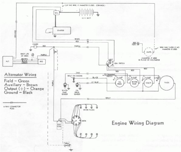
Here's an early wiring diagram that's representative of what you had in a 79. It doesn't show the breaker, but it would be in the red wire between the solenoid and the ignition switch, real close to the solenoid. It also doesn't show the NSS (neutral safety switch), it would be in the white wire between the keyswitch and the solenoid. At the ammeter where it says "red to ign switch" that goes to the Bat terminal on the switch along with the 10 gauge Red wire previously mentioned. That ammeter wiring is a long and winding road that the charging circuit for the battery follows. It goes from the alternator up to the dash, through the ammeter, through the keyswitch and back to the solenoid where it connects with the battery cable
|
Posted By: NeilMcG
Date Posted: December-20-2022 at 7:58pm
|
Thanks Ken, that was very helpful, The wiring is still in place but I'm leaning on using bus bars for all dash power. I drew up a schematic on cad and it seems to show that it can be cleaned up significantly while getting rid of daisy chaining and putting it all in parallel. I got your message...will do. |