 Boats For Sale:


2012 SAN 210 PCM 40 to 80 series Transmission swap |
Post Reply 
|
| Author | |
Liquiddreams 
Newbie 
Joined: September-02-2020 Location: Georgia Status: Offline Points: 34 |
 Post Options Post Options
") Thanks(0) Thanks(0)
 Quote Reply Quote Reply
 Topic: 2012 SAN 210 PCM 40 to 80 series Transmission swap Topic: 2012 SAN 210 PCM 40 to 80 series Transmission swapPosted: September-10-2020 at 9:51pm |
|
I recently completed a PCM 40 series transmission to PCM 80
series transmission swap in my 2012 SAN 210 TE. I took some pictures along the
way and I am going to post them for people to use my experience to make theirs
a little easier. I will say overall if you have the tools handy it was not that
big of a job in my opinion, but I did run into some speed bumps along the way.
Backstory, I bought this boat used from a dealer in South Carolina. Within a
few weeks the transmission started slipping due to water intrusion. My mistake
was I checked the fluids over before test run and not after. Once I got into
the replacement I found evidence that either they or the owner before me knew
of the issues. However, I bought it so I fixed it. I am not bashing them, but rather
just giving the story of how I got here. LOL So instead of rebuilding the
current 40 series transmission I decided to completely swap to the 80 series.
So it began... First, I added an Eye-bolt to the ceiling of my garage to
utilize for minimal lifting of the rear of the engine. Second, I cut blocks to
go under the hoisting rings on either side of the motor to support the weight
of the motor once I removed the rear mounts. Then I removed the prop. This was my first speed bump. The
prop had not been removed in a number of years and had almost fused with the
shaft. I tried multiple methods that worked for me in the past including heat
to no avail. I broke down and bought a ACME C-Clamp style puller to overcome
this speed bump, so I now have one in my tool kit. Once this was complete I
moved inside the boat to clear room to work. I removed the floor to access the
V-drive and make more room for removal.
Next, I went through the rear hatch to remove starter, Oil
filter w/hanger, wires for the sender, and the shift cable.
At this point I removed the inlet and outlet water hoses
from the v-drive and bolts from the coupler. I then attempted to un-mate the couplers.
Well… This was speed bump 2… they had been married a long
time and did not want to be separated either. Even after I broke the coupling mate
up the shaft side coupler did not want to come off the shaft. With the close
proximity to the fuel tank I was hesitant about introducing heat with a torch,
so I tried multiple ways to get it off. Even bent a harmonic balancer puller
trying to get this thing off. After seeing a video of a puller online I
purchased it since it utilized four bolts to pull more evenly. However, it was
going to be about 5 days for delivery. So I decided to remove the shaft through
the floor with the coupler still attached. In order to accomplish this I had to
loosen the brackets for the forward ballasts and the fuel tank brackets to
slide the fuel tank back to get enough clearance to remove the shaft with
coupler. Once the shaft was removed I supported the rear of the motor
utilizing straps to the eyebolt and wood blocks under the hoist rings on either
side. Now that it was secure I could start the removal process. I
removed the shift linkage bracket that happened to be held in place by two of
the nuts that held the V-drive to the transmission. Then finished removing the 8
nuts from the rest of the studs that attached the v-drive to the tranmssion.
I move back to the forward facing part of the v-drive and
removed the intake water hoses for the ballast make more room for the removal
process.
At this point I supported the v-drive with wood blocks and I
removed the four bolts that attach the V-drive to the mount (2 on either side).
Remove the v-drive and set out of the way.
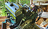
After the v-drive was removed I figured the transmission
would not fit through the v-drive mount so I removed the 4 bolts connecting the
mount to the stringer brackets and moved it out of the way. Once the v-drive
mount was out of the way I removed the four main transmission mount bolts out
of the mounts and loosened them to swing them out of the way. In the pic below
you can see the top bolt, but two are behind the exhaust and the last one is under
the one viewable in the picture. Warning: Now all weight of the motor on that
side will be on your blocks and straps.
Now that the engine is supported I used the wood blocks to
support the transmission so I could remove the four main transmission to bell
housing bolts. At this point I removed the transmission and got it out of the
way.
Now you have a clear view into your bell housing and can see
the damper plate. Now we are ready to remove the bell housing. The first thing
I did was removed the smaller dust shield bolts along the bottom of the bell
housing. I believe there were 6 in total. Then removed the grounding wires and
used two nuts to remove the grounding studs on both sides of the block. There
was one bolt on the very top of the bell housing and then two hidden bolts.
These took a minute to fins and I had to research to find them. Thanks to a
person that posted about GM blocks having a hidden bolt I was able to find the
one identified in the starter hole. There is a plate behind the exhaust that
covered a similar hole to the starter hole with a hidden bolt. The hidden bolts
in the holes were twelve point bolts if you start trying to pull those out.
Now, you can remove the bell housing to access the damper
plate. Remove the 6 bolts around the exterior of the damper plate to remove it
from the flywheel.
After the damper plate is removed I had clear visibility of
the flywheel and how much rust was on it. With the amount of rust on the
flywheel I took the opportunity to clean off some of the rust.
Once the flywheel I began the installation process starting
with the installation of the new damper plate.
Reinstalled the bell housing and dust shield.
Removed the new transmission out of the box and prepare it
to install by putting all of the necessary fittings in to install the new
transmission cooler.
Now I took advantage of the eye-bolt and used a small strap
to help me lift the transmission in place. Installed the four main bolts that were holding the transmission in place to the bell housing.
I took advantage of the open space and installed the hoses
for the transmission cooler and then the v-drive mount. I also loosely
installed the transmission mounts to help support the transmission, but these
will have to be uninstalled for the alignment part of the installation.
I then took the time to clean up the v-drive coupler and
remove a majority of the rust (I find out later that it was not enough though).
I use the eye-bolt and a small strap to once again help with the installation process.
I had to remove the studs from the old transmission to make this installation (once
again using the two nut process for removal).
With the two major components in I went ahead and installed
the new 12” transmission cooler and lines in the place of the old 5-6 inch one
that came stock. I was able to use the same bracket and just cut some length
off of the old water outlet hose.
Now I started the smaller component installation. Starter, sender
wires, oil filter w/bracket. As I am going through this process I am slowly
trying to clean up any rust that I can.
Here is where the third speed bump came in. I took the time
to straight file the face of the shaft coupler and clean up any corrosion/rust.
I even cleaned and lapped the shaft for proper fit. I installed the shaft
coupler and the PPS Shaft seal onto the shaft as I was putting the shaft back
in. I then tried to begin the alignment process. Well it did not mate up and
after some discussions on one of the forums I decided that it must be to out of
alignment to mate (this was a hard decision and one I would regret). So I
started moving the motor around to get it in alignment to get the no resistance
mate. However, if you look at the picture below the faces were almost perfectly
in align already, so the movement was a shot in the dark.
Well, after a lot of movement and no luck in mating. I
removed the coupler and pushed the shaft aft. Well… Still no mate. So I
inspected the v-drive coupler and found that there was some pitting in the
female side of the mate that was not allowing the couplers to mate. After doing
some minor improvements on the female side to remove the pitting I was able to
get a perfect resistance free mate. So I installed the coupler back on the shaft
and started the alignment process again. Note: I will always assure a perfect
mate with the couplers alone before installing the shaft. I made sure the shaft
was center of the outlet on the bottom of the boat (BTW It wasn’t even close
thanks to my above speed bump). Once centered of the outlet (using old piece of
hose to help with this). I went back up top to align the motor as best I could to
the center of the shaft without mating. Once it was pretty center visibly I
mated the coupler with no resistance and started the feeler gauge process.
Using the method outlined in the Owner’s manual I did the alignment and bolted
everything back up. Installed all of the hoses and wires back to their original
place. Moved the fuel tank and ballasts back to their spots. Took it for a test
drive. Only issue was a slight leak around the shaft seal that was due to the
allen screws not aligning to the indentions.
Hope this will help someone in the future that might take on
this task. Searching I was limited on information that was out there on this
installation, so I thought I would add some to assist. |
|
 |
|
|
8122pbrainard
Grand Poobah 

Joined: September-14-2006 Location: Three Lakes Wi. Status: Offline Points: 41040 |
Post Options
Thanks(0)
Quote Reply
Posted: September-11-2020 at 5:10am |
|
William,
Very nice. Thanks for the effort.
 |
|
|
|
|
KENO
Grand Poobah
Joined: June-06-2004 Location: United States Status: Offline Points: 10643 |
Post Options
Thanks(0)
Quote Reply
Posted: September-11-2020 at 6:29am |
|
I think you need to do a little clarifyng on the hidden bolts. See your PM inbox |
|
|
|
|
Liquiddreams
Newbie
Joined: September-02-2020 Location: Georgia Status: Offline Points: 34 |
Post Options
Thanks(1)
Quote Reply
Posted: September-11-2020 at 7:20am |
|
Good catch Keno. I'll have to edit that.
|
|
|
|
|
KENO
Grand Poobah
Joined: June-06-2004 Location: United States Status: Offline Points: 10643 |
Post Options
Thanks(0)
Quote Reply
Posted: September-11-2020 at 7:32am |
|
At least you know that somebody was interested and read the post
Good job on the swap and the post, I think a lot of us learned a lot of things along the way  Ya might call it a multi forum team effort But.............. you did all the heavy lifting
|
|
|
|
|
Liquiddreams
Newbie
Joined: September-02-2020 Location: Georgia Status: Offline Points: 34 |
Post Options
Thanks(0)
Quote Reply
Posted: September-11-2020 at 7:56am |
|
I think I got it fixed now. It was most definitely a multi forum team effort and that support was definitely appreciated. It's times like those that you get to see some of the real good that you can get out of the internet.
|
|
|
|
|
fanofccfan
Platinum Member 

Joined: December-13-2009 Location: North Bend NE Status: Offline Points: 1721 |
Post Options
Thanks(0)
Quote Reply
Posted: September-11-2020 at 9:36am |
|
Awesome write up that I hope I never have to refer to for guidance!
|
|
|
2004 196 LE Ski 1969 Marauder 19 1978 Ski
|
|
|
|
|
Liquiddreams
Newbie
Joined: September-02-2020 Location: Georgia Status: Offline Points: 34 |
Post Options
Thanks(0)
Quote Reply
Posted: September-12-2020 at 10:37pm |
 I hope you don't either. I wouldn't wish it on anyone. I hope you don't either. I wouldn't wish it on anyone. |
|
|
|
|
Post Reply
|
|
 Tweet
Tweet
|
| Forum Jump | Forum Permissions You cannot post new topics in this forum You cannot reply to topics in this forum You cannot delete your posts in this forum You cannot edit your posts in this forum You cannot create polls in this forum You cannot vote in polls in this forum |


 Topic Options
 fanofccfan wrote: