 Boats For Sale:


79 nautique rebuild |
Post Reply 
|
Page <1 34567 12> |
| Author | |
KENO 
Grand Poobah 
Joined: June-06-2004 Location: United States Status: Offline Points: 10644 |
 Post Options Post Options
") Thanks(0) Thanks(0)
 Quote Reply Quote Reply
 Posted: July-23-2021 at 6:29am Posted: July-23-2021 at 6:29am |
|
Going back to the thread in the link below, what has happened since then?
Did you buy a new harness for the engine and the boat or are you unraveling the rats nest that came with the boat? |
|
 |
|
|
KENO
Grand Poobah
Joined: June-06-2004 Location: United States Status: Offline Points: 10644 |
Post Options
Thanks(0)
Quote Reply
Posted: July-23-2021 at 11:27am |
|
From your PN post, I can see that you got a new PMGR starter and new harnesses
 If you identify the alternator, it'll be a lot easier to come up with some helpful info and probably a good diagram. The harness must have an 8 plug connector or is it something different. What do you have for wire colors at the connector? The chopped off 10 gauge Orange wire is normal for a harness built for no ammeter.
|
|
|
|
|
wayoutthere
Senior Member 
Joined: February-28-2020 Location: Florida Status: Offline Points: 391 |
Post Options
Thanks(0)
Quote Reply
Posted: July-23-2021 at 2:24pm |
 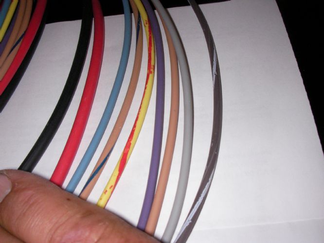   
The new wire harness is a 9 pin, the engine and boat side have a brown w/blu tracer but the dash harness does not, maybe the dash side is 8 pin, (i'll check), the dash and boat harnessess are installed but not yet connected or cut to length. The purple wire from the alternator goes to the coil, i left that in place. The rest of original wiring harness was cut and spliced from dash to engine, there was cut wires stuffed and wrapped up from dash to engine. The new starter is an arco with attached solenoid. Edit in: there was 3 wires on the alternator purple to coil + 10g red spliced into 10g orange black ground. What happened, well back then i still couldn't verify the wiring and with all the work still on the list ! Oh, and as you can see the wiring harness is not numbered. |
|
|
|
|
KENO
Grand Poobah
Joined: June-06-2004 Location: United States Status: Offline Points: 10644 |
Post Options
Thanks(0)
Quote Reply
Posted: July-23-2021 at 5:45pm |
|
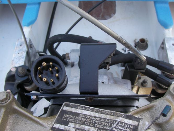
Looks like a Mercruiser style plug and harness.
Also looks like an internally regulated alternator and you mentioned the new Arco starter. If you follow the diagram below (from the TRB collection) it'll get you all wired up on the engine side in spite of you having a 9 plug Mercruiser connector setup. I'd save it, rotate it, blow it up and print it.  Looking at your engine side harness picture, the extra wire is the brown and blue wire. I'd just call it an "installed spare", you don't need it. From the engine side plug wire it like below 10 gauge black...........ground to engine block 10 gauge red..............to output of the breaker other end on boat harness goes to 20 amp fuse or breaker on dash, then to BAT terminal on the keyswitch light blue.........to oil pressure sending unit other end on boat harness is the signal to the gauge brown and blue.......installed spare yellow/red......... to one terminal of the neutral safety switch, then from the switch a short length of the same wire to the "S" terminal on the slave solenoid(relay) on the back of the engine other end on boat harness goes to "S" terminal on keyswitch purple......like in the TRB diagram, it's gonna go 3 places. It will need to branch off to the coil positive terminal, the electric choke and the alternator excitation. other end on boat harness goes to "I" terminal on keyswitch It could branch off at the ballast resistor input terminal or in the harness like shown in the above drawing. PCM did it both ways at different times. tan...........to water temperature sending unit other end is signal to the gauge gray ........to the coil negative terminal Black and white......I guess I don't see a use for that wire either Call it another "installed spare" Other wires and wiring..............per the diagram the PMGR starter and relay wired as shown, alternator output wire from the output terminal to the breaker as shown. 12 volts to the dash instruments comes from "I" terminal on the keyswitch 12 volts to lights, bilge pump, blower(anything you want powered all the time comes from the Bat terminal on the keyswitch. Your charging path is really pretty direct with this setup from the alternator to the breaker to the solenoid/relay to the battery. With the old ammeter setup, the charging current went up to the dash, through the ammeter, to the keyswitch and then back to the relay. A long and winding road compared to the voltmeter setup. I think you have most of this figured out already, and just remember the attached TRB diagram is your best friend. And one last thing distributor purple wire to coil positive and black to coil negative.
|
|
|
|
|
wayoutthere
Senior Member
Joined: February-28-2020 Location: Florida Status: Offline Points: 391 |
Post Options
Thanks(0)
Quote Reply
Posted: July-23-2021 at 7:12pm |
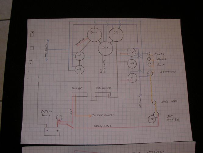 
Thanks keno, i made some drawings earlier and see the alterations based off your explanation which is very plainly understood. The picture you attached i cant read either on screen or the saved version. I have to have it all on paper to see and understand what's going on with no deleted or moved parts in the drawing ike the ballast and solenoid, otherwise it all goes down hill. I'll have to ammend and re draw the wiring for this boat probably several times this weekend until one drawing has all the answers and is correct. Thanks again for the fast help and very clear explanation. |
|
|
|
|
wayoutthere
Senior Member
Joined: February-28-2020 Location: Florida Status: Offline Points: 391 |
Post Options
Thanks(0)
Quote Reply
Posted: July-23-2021 at 7:21pm |
|
Why does 10g red go from alternator to breaker to solenoid to battery?
Can't it go from alternator to battery I think in terms of flow. battery to a to b to c, stop, next wire from key to a to b to c, stop and wire gauge as volume. Like my lights, the wire goes from switch to gauges then branches off to bow and stern lights. |
|
|
|
|
KENO
Grand Poobah
Joined: June-06-2004 Location: United States Status: Offline Points: 10644 |
Post Options
Thanks(0)
Quote Reply
Posted: July-23-2021 at 9:05pm |
|
It could go right to the battery, but then you're running a long piece of say 10 gauge wire to the battery or the way they've done it, you have a short piece of 10 gauge to the breaker, a really short piece to the solenoid and then current flows through the 2 gauge cable to the battery.
I guess you could call it a combination of convenience and efficiency There are a few different ways to do it, the diagram shows what PCM did. I don't know if this diagram will work any better, it's the original before I cleverly marked it up and it even more cleverly, shrunk itself on me. Only differences are the purple wire and how the excitation, choke and ignition wires tie together and pin 4 being in the wrong spot. (just compare to the other drawing if possible) I don't know if it will show up or print better, but I figure it's worth trying  |
|
|
|
|
wayoutthere
Senior Member
Joined: February-28-2020 Location: Florida Status: Offline Points: 391 |
Post Options
Thanks(0)
Quote Reply
Posted: July-24-2021 at 9:56am |
|
It's crystal clear, thanks keno !
I went to catholic school k-8, so electricity- ohms volt resitance etc, the metric and .000's of an inch are all black magic witchcraft and devil math that cannot be explained or understood so stay away from it. I'm a few wires away from having it all make sense, but i keep seeing direct shorts. ie from battery to breaker, alt to breaker and all tied together to the starter Battery is the power source ground it to the block, brush the red around and see sparks, now connect the alternator to the other side the breaker, thru black magic it's a power source, start the engine and send the black magic into the other side of the breaker bang direct short Are they saving wire and $ with it tied together? Does 12 volt go back and forth thru witchcraft ? See how i'm thinking flow chart battery to all points then back to the battery and connecting 12 volt points to the other side of a 12 volt points are direct shorts? Aren't you glad your trying to help !
|
|
|
|
|
SNobsessed
Grand Poobah
Joined: October-21-2007 Location: IA Status: Offline Points: 7102 |
Post Options
Thanks(0)
Quote Reply
Posted: July-24-2021 at 11:01am |
|
direct short is when (+) of battery goes to (-) with no resistance.
If you are using ohm meter & getting zero ohms on the connections (that are all on same polarity side of battery), that is a good thing. Think of electricity are water. Wires are the pipes. You can have parallel pipes but that is a waste of pipe.
|
|
|
“Beer is proof that God loves us and wants us to be happy.”
Ben Franklin |
|
|
|
|
wayoutthere
Senior Member
Joined: February-28-2020 Location: Florida Status: Offline Points: 391 |
Post Options
Thanks(0)
Quote Reply
Posted: July-24-2021 at 1:07pm |
   
Thank you guys, could not have got it without your help. This is points converted to electric with new starter, new gauges, new harness (no ballast resistor, remote solenoid or splicing into original harness mess) Behind the dash Start - run & charge Total overview w/ accy's, i'll make a clean overview and they all get saved in an envelope with all the manuals templates receipts etc etc. Thank you again.
|
|
|
|
|
KENO
Grand Poobah
Joined: June-06-2004 Location: United States Status: Offline Points: 10644 |
Post Options
Thanks(0)
Quote Reply
Posted: July-24-2021 at 8:36pm |
The mention of no remote solenoid is an attention getter. When Ford started using the PMGR starter in autos, they retained the remote solenoid and all the marinizations of the Ford using that starter used the remote solenoid and even Chevy people adapted Ford remote solenoids for various start issues, you might want to think about keeping the remote solenoid. And every marine engine outfit uses a remote solenoid whether it's a Ford or GM engine with a PMGR starter. It'll work without the remote solenoid, but I'd run a 10 gauge or so wire from the keyswitch to the neutral safety switch and then to the starter solenoid if you're ditching the remote solenoid. Then if you have starter issues, the first thing to do would be to wire in the remote solenoid. I'm getting tired of writing remote solenoid, so I'll just leave it at that PS.........I'm still glad to be helping
|
|
|
|
|
wayoutthere
Senior Member
Joined: February-28-2020 Location: Florida Status: Offline Points: 391 |
Post Options
Thanks(0)
Quote Reply
Posted: July-24-2021 at 9:28pm |
|
Thanks keno
Why is there a solenoid on the starter if it still needs a remote ? Does the yellow w/ red start wire go to the solenoid on the starter or just the remote
Is this just a re route of battery cables from battery to remote to starter ? Is there any other wiring changes? Does anyone want to buy a ski boat that needs wiring ? All ectrical stuff is here. I'll order the new shaft, align it and bed /glass the stern tube. |
|
|
|
|
KENO
Grand Poobah
Joined: June-06-2004 Location: United States Status: Offline Points: 10644 |
Post Options
Thanks(0)
Quote Reply
Posted: July-25-2021 at 7:16am |
|
It doesn't absolutely need the remote but it gives better voltage to the solenoid on the starter due to a shorter wire run from the battery to the starter mounted solenoid "S" terminal.
It doesn't have to go up to the keyswitch and back.(although it does for the remote solenoid) With the old Ford starter the remote solenoid carried all of the starter motor current,(hundreds of amps for a short time) and with the new starter the remote carries only the small amount of current needed to energize the starter mounted solenoid.(maybe 10 or so amps) then that solenoid has to carry the starting current to the motor. It's hard to explain, may not seem to make much sense but works better especially in a boat where the distance between the keyswitch, battery and starter can be a lot longer than in a car. It would get wired like the previous diagram shows (and if you do sell the boat, you hand the guy the colored TRB diagram that's pretty easy to follow) Or do what you're planning and it may work just fine, really |
|
|
|
|
wayoutthere
Senior Member
Joined: February-28-2020 Location: Florida Status: Offline Points: 391 |
Post Options
Thanks(0)
Quote Reply
Posted: July-25-2021 at 8:54am |
|
This is way over my head,
The remote had 2 battery cables on the same side 1 from the battery the other to the starter, there was a10g jumper over to the breaker the yellow/red start wire wasnt on the remote. There was more wires on the breaker and remote than in any schematic. No way i can wire it and be confident when it can be wired all kinds of ways Which way is correct (safe and reliable) and which way is wired to work (boom) I thought the new starter was the better way to go, all the parts starter harness all bought together from same ski boat place, i'm confused but not surprised, cut my losses on it
|
|
|
|
|
67 ski nat
Platinum Member 
Joined: July-19-2018 Location: Santa rosa Status: Offline Points: 1180 |
Post Options
Thanks(0)
Quote Reply
Posted: July-25-2021 at 9:06am |
|
Hey WOT. Do not get discouraged
This is the last 1% Your doing great job and your so close Maybe a little confusing but actually very doable Keep going with kens help you will figure out by end of today ‘If it was easy everyone would do it |
|
|
|
|
KENO
Grand Poobah
Joined: June-06-2004 Location: United States Status: Offline Points: 10644 |
Post Options
Thanks(0)
Quote Reply
Posted: July-25-2021 at 9:13am |
|
If you wire it like this diagram from a couple of days ago, you'll be all set. It works
it's for the later internally regulated alternator, the newer PMGR starter and electronic ignition and setup for a voltmeter, all of which you have Use the colors I mentioned a couple days ago to go with the diagram. It does say in the legend in the lower right that it's for a one wire older starter, but he forgot to change that when he modified the drawing to show the newer PMGR starter
|
|
|
|
|
wayoutthere
Senior Member
Joined: February-28-2020 Location: Florida Status: Offline Points: 391 |
Post Options
Thanks(0)
Quote Reply
Posted: July-25-2021 at 11:46am |
|
So as the above diagram excluding the green exciter the ballast and + to choke from the ballast.
"Batterry cable" to battery switch to remote A side from A side to starter. Yellow w/red start wire to S, what gauge wire from B side of remote to solenoid (is that a typo and should be yellow w/red start wire. Battery switch is needed and will be between the battery (which is under the rear seat) and starter. I appreciate the help and motivation, i'm outside working on it now (seperate accy loom and fastener points for all electrical) and will follow up w/ the pm. Thank you
|
|
|
|
|
KENO
Grand Poobah
Joined: June-06-2004 Location: United States Status: Offline Points: 10644 |
Post Options
Thanks(0)
Quote Reply
Posted: July-25-2021 at 12:47pm |
|
From the "B" side of the remote solenoid a piece of 10 gauge is good.
I'd probably use a piece of red 10 gauge from the extra length you probably have in the boat side harness. I'm not sure why he colored it yellow, Arco sends a piece of red 10 gauge with the "kit". If you didn't get the kit, you get the starter only without that wire, and pay a few bucks less. Just to be sure, from the purple ignition wire, you still want a wire to the choke(usually red) and the excitation to the alternator (usually green or green and yellow) so that all 3 components get fed from the same spot.
|
|
|
|
|
wayoutthere
Senior Member
Joined: February-28-2020 Location: Florida Status: Offline Points: 391 |
Post Options
Thanks(0)
Quote Reply
Posted: July-31-2021 at 9:18pm |
Wired the dash, it's tidier than the pics show, then made an accy and fuel sender harness- dash side and boat side, the boat side was put into the loom in sections were it splits off for the bilge pump and ground, the ground is for everything at the ransom. No connections in the loom, no under water connections unless you count the bilge pump. All screws/cushion clamps got the 4200. The harness is cushion clamped then the wires come out and loop thru another one, obviously not abc color coded, but there wasn't enough length of those colors left over, it's all tinned marine grade wire and in a seperate loom. Rubrail tomorrow so the stern light can be centered with the rail cap, then finish the aft accy's. Haven't looked at the engine, the broken riser bolt will be dealt with when the battery is in.
|
|
|
|
|
wayoutthere
Senior Member
Joined: February-28-2020 Location: Florida Status: Offline Points: 391 |
Post Options
Thanks(0)
Quote Reply
Posted: July-31-2021 at 9:28pm |
 
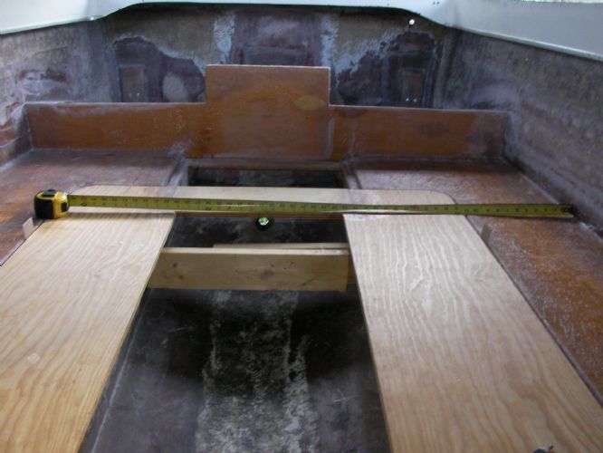
Trailer lights and goal posts are done, front bump stop after battery and full fuel to set tongue weight. Should land within 1/2 inch on the trailer everytime
|
|
|
|
|
67 ski nat
Platinum Member
Joined: July-19-2018 Location: Santa rosa Status: Offline Points: 1180 |
Post Options
Thanks(0)
Quote Reply
Posted: August-01-2021 at 6:27am |
|
Wiring well done. Looks clean and tidy
|
|
|
|
|
8122pbrainard
Grand Poobah

Joined: September-14-2006 Location: Three Lakes Wi. Status: Offline Points: 41040 |
Post Options
Thanks(1)
Quote Reply
Posted: August-01-2021 at 6:37am |
|
Dan,
Again I'm impressed at your work and to the extent you are going.
 |
|
|
|
|
Nautiquehunter
Platinum Member

Joined: December-31-2008 Location: Lake Lanier GA Status: Offline Points: 1010 |
Post Options
Thanks(0)
Quote Reply
Posted: August-01-2021 at 7:16am |
|
Guide poles look a little tight?
|
|
|
|
|
wayoutthere
Senior Member
Joined: February-28-2020 Location: Florida Status: Offline Points: 391 |
Post Options
Thanks(0)
Quote Reply
Posted: August-02-2021 at 4:57am |
   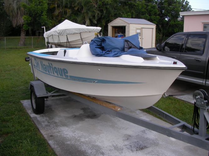
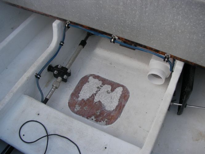
A while back i got to job of closing up the joint from about the dash to the bow, it's the only part that wasn't bonded from the inside. Looked like after years of bumping into everything she was popping loose, the original fit is what it is so the deck sagged and some of the rivets where damn near a 45 or pulled right thru, so a kicker and some old rubrail screws got it all lined up and squeezed back together. Yesterday the rest of the old silicone was cut out and the joint scrubbed out with a toothbrush. After silicone around the perimeter for fun i filled all the holes with silicone, whether it stops or slows the little dribbles or not we'll see. Old rubrail went right on in the original holes with screws 1 size bigger with nice big flat heads that i got from overtons, i went around sevral times just turning enough to close the gap and not crush it out of shape, but it is 42 years old. I read some threads about installing the rope, luckily there was plenty of 3/8 anchor line hanging in the shed and it went right in. 8122, appreciate that, i sweat all the details but lack the skills so the finished product never looks like the picture in my head. Nautiquehunter, they are tight, but the boat will most likely be moved 3 inches forward for tongue weight and that will open the gap, right now there's a 1/4 inch. plus side if they don't work is i'll have to make another pair, and after the boat is done there won't be anything to do but sit at the welder all day. |
|
|
|
|
wayoutthere
Senior Member
Joined: February-28-2020 Location: Florida Status: Offline Points: 391 |
Post Options
Thanks(0)
Quote Reply
Posted: August-12-2021 at 6:20pm |
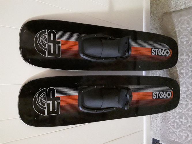 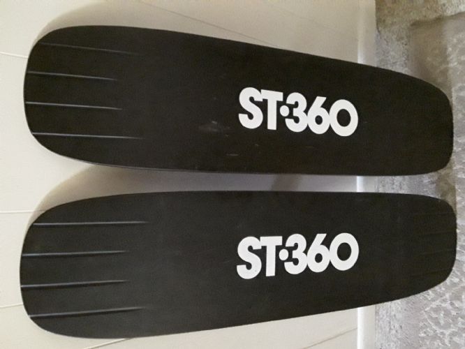
I bought these trick skis from member ccfan today, they are very well maintained, in near new condition from the 80's. Nice guy, honest and straight forward, i would trust to buy from him again. Scott, if you end up breezing thru this thread, it was a pleasure to meet you, thank you again for such a great deal on a fantastic pair of skis. |
|
|
|
|
wayoutthere
Senior Member
Joined: February-28-2020 Location: Florida Status: Offline Points: 391 |
Post Options
Thanks(0)
Quote Reply
Posted: August-21-2021 at 3:48pm |
              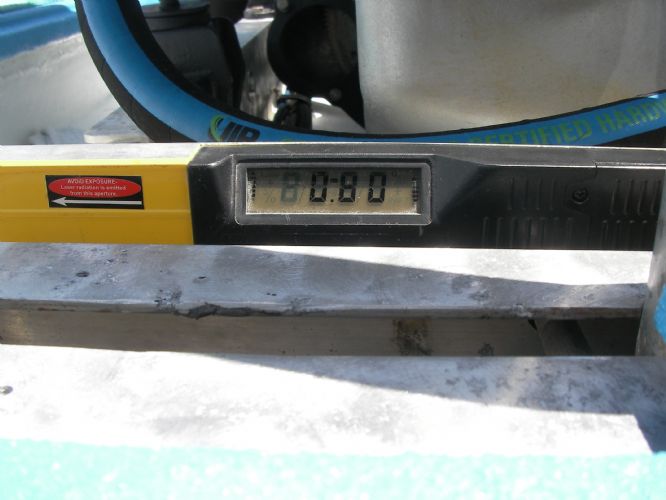  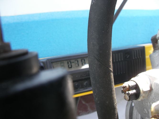  
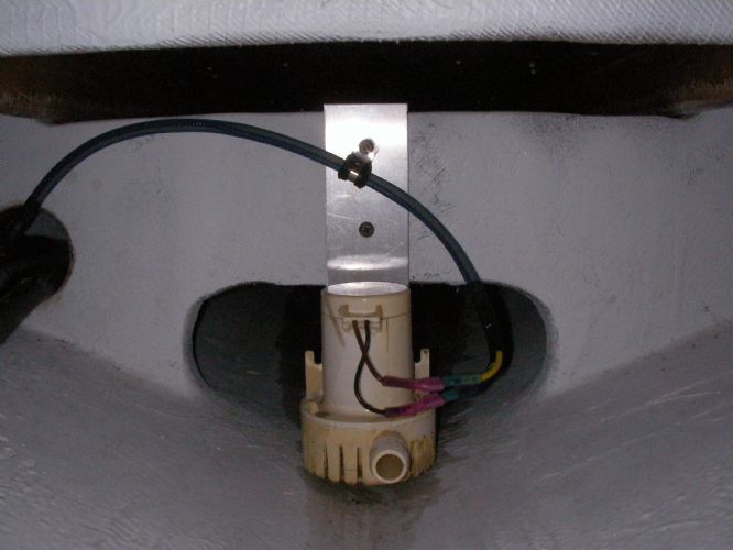
the broken riser bolt came out by finger and the risers are on. Anyone ever says your going thru too much trouble for no reason setting the boat up on water levels, pulling strings, dropping plumb bobs, finding centerline, locating and levelling stringers, measuring, double checking 10 x's and staying on bubble all the way thru the job, let them know alignment starts at the corner of dog box and exhaust riser. lucky thing that shaft being bent and it not getting aligned bedded and glassed before the risers went on. |
|
|
|
|
wayoutthere
Senior Member
Joined: February-28-2020 Location: Florida Status: Offline Points: 391 |
Post Options
Thanks(0)
Quote Reply
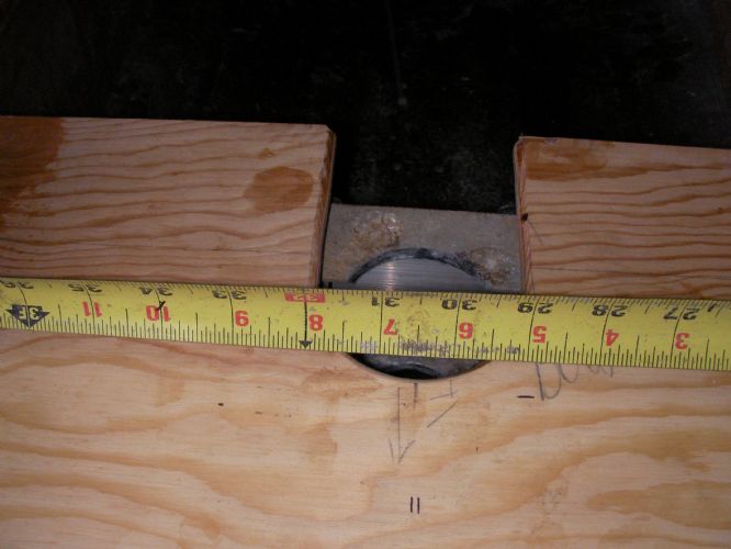
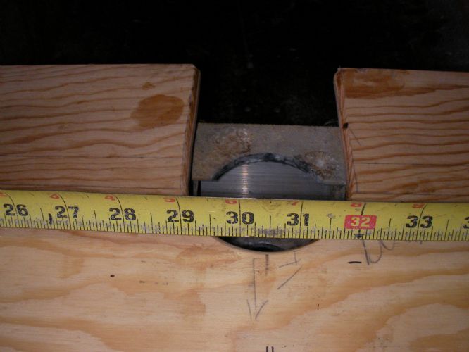
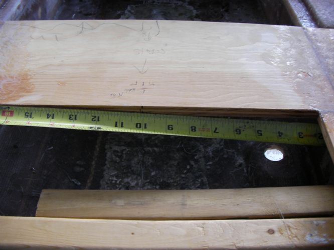
Posted: August-23-2021 at 2:05pm |
  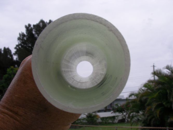  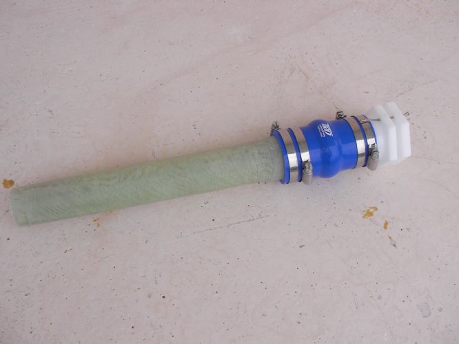 
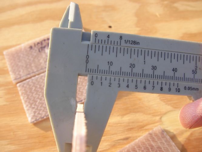
Toying with the idea of a fiberglass stern tube, the bronze tube doesn't fit the hull very good, with the bent shaft it had to be shimmed up over a 1/2 inch in the front and there was quite a bit of bedding compound on it. Water stains on the bronze show water was getting inbetween it and the hull but it wasn't leaking into the boat. The old bearing fits better in the glass tube than it does in the bronze one, ( less slop). I think it can slide down the shaft and get scribed, cut and ground to better fit the hull. There is just about 560 sqaure inches of 1700 bi-axial material (no mat) each piece made 2 laps so its 8 layers and just under 3/16 thick. I spun it on the grinder to clean it up and turn the bell end to 1 3/4 inches to fit the new stuffing box hose. |
|
|
|
|
67 ski nat
Platinum Member
Joined: July-19-2018 Location: Santa rosa Status: Offline Points: 1180 |
Post Options
Thanks(0)
Quote Reply
Posted: August-24-2021 at 9:27am |
|
WOT You do crazy good work
|
|
|
|
|
wayoutthere
Senior Member
Joined: February-28-2020 Location: Florida Status: Offline Points: 391 |
Post Options
Thanks(0)
Quote Reply
Posted: August-25-2021 at 7:45pm |
|
Thanks 67,
i'm just wanting options so the least amount of bedding compound is used. Ordered exhaust hose and fuel line this morning from below link, bought from them before good prices fast shipping from florida warehouse, the stuff will be here tomorrow. https://marinepartssource.com/ Yesterday i mounted the battery switch, starter and solenoid then mocked up all the cables using vinyl tubing. Today i picked up the battery and they made all the cables up, (Interstate batteries) Fingers crossed the carb works, the dizzy makes lightning and alternator alternates, start up is a few days away weather permitting.
|
|
|
|
|
gun-driver
Grand Poobah
Joined: July-18-2008 Location: Pittsburgh, Pa Status: Offline Points: 4112 |
Post Options
Thanks(0)
Quote Reply
Posted: August-25-2021 at 8:31pm |
Why ? And what do you mean by this “ alignment starts at the corner of dog box and exhaust riser. “
|
|
|
|
|
Post Reply
|
Page <1 34567 12> |
 Tweet
Tweet
|
| Forum Jump | Forum Permissions You cannot post new topics in this forum You cannot reply to topics in this forum You cannot delete your posts in this forum You cannot edit your posts in this forum You cannot create polls in this forum You cannot vote in polls in this forum |


 Topic Options
 wayoutthere wrote: