 Boats For Sale:


79 nautique rebuild |
Post Reply 
|
Page <1 23456 12> |
| Author | ||
KENO 
Grand Poobah 
Joined: June-06-2004 Location: United States Status: Offline Points: 10638 |
 Post Options Post Options
") Thanks(0) Thanks(0)
 Quote Reply Quote Reply
 Posted: June-26-2021 at 6:45pm Posted: June-26-2021 at 6:45pm |
|
|
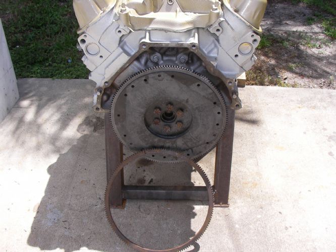
Well............ there's some bad news to be given here
You have a flywheel for a later 302 when they liked to call them 5.0 engines and it takes metric fasteners. It's also 50 oz imbalance on that flywheel and you want one with 28 oz imbalance otherwise you'll be able to make milkshakes on top of the engine if you were to install it and the damper plate with some bolts that would fit. Or in other words.........don't even think about trying to use that flywheel. The changes happened around 1983 or so for reasons known only to Ford The earlier 157 tooth flywheel that was on your engine was, like mentioned earlier a cross reference to a 67 Mustang with a 289 and a 4 speed which had 28 oz imbalance. So.........you either need to get your old flywheel back or go back in this thread to the part numbers for the right flywheel and get one of them, then your SAE bolts will fit and you already know you need to trim it and use only 3 bolts and you'll be back in business.  . .Just tell the parts guy what you need with the part numbers given earlier because the Ford marine 351 flywheel isn't on any 351 automotive engine. Once again only Ford knows why they did things the way they did |
||
 |
||
|
Gary S
Grand Poobah

Joined: November-30-2006 Location: Illinois Status: Offline Points: 14096 |
Post Options
Thanks(0)
Quote Reply
Posted: June-26-2021 at 8:16pm |
|
I have read that the reason for the change to 50 oz balance was because it was cheaper to produce. And when you think of how many 5.0 Lincoln,Mercury,Ford, and Ford trucks built with them in compared to the 5.8 it sounds plausible. When they are building millions even 50 cents is something.
|
||
|
||
|
wayoutthere
Senior Member 
Joined: February-28-2020 Location: Florida Status: Offline Points: 391 |
Post Options
Thanks(0)
Quote Reply
Posted: June-26-2021 at 8:34pm |
|
|
Keno, that's not bad news at all, bad news would've been finding out after the engine was installed.
I'll copy the numbers and notes then take it all up there monday, meantime i'll price check it so i can make a decision, hopefully theres no restocking fee, i told them what it was. Appreciate it everybody, thank you for the help the part #'s, all the tech and advice. It's always the engines that screw the job
|
||
|
||
|
KENO
Grand Poobah
Joined: June-06-2004 Location: United States Status: Offline Points: 10638 |
Post Options
Thanks(0)
Quote Reply
Posted: June-27-2021 at 5:35am |
|
|
If the shop has their doubts, give them the Ford part number cast into the flywheel to cross reference.
If you get the old one back, like mentioned earlier you can get a ring gear pretty cheap and do it yourself. Maybe Pete will let you in on his source for a 10 dollar ring gear........maybe not He seems to have missed this question below from a little earlier in this same thread You can find one for under 20 though at that auto parts place that he just loves to bash. I think it ends in Zone
|
||
|
||
|
67 ski nat
Platinum Member 
Joined: July-19-2018 Location: Santa rosa Status: Offline Points: 1180 |
Post Options
Thanks(0)
Quote Reply
Posted: June-27-2021 at 9:48am |
|
|
Nice work Ken
|
||
|
||
|
wayoutthere
Senior Member
Joined: February-28-2020 Location: Florida Status: Offline Points: 391 |
Post Options
Thanks(0)
Quote Reply
Posted: June-29-2021 at 7:09pm |
|
|
Hooorrraaayyyy !!!!!!! More engine BS !!!
New flywheel returned, "why whats wrong with it, it's 157 tooth" I gave them the part #'s for the ring gear and now waiting. Last week i ordered an oil drain line kit "for 351w old ski boats" it came today and it is the wrong thread, not to mention if you wanted yo use the 90* fitting on the pan it won't work because of the pushlock thing. Another part from super awesome parts we know our *************** dot com that's wrong. I either need a clean good running take out or the whole thing gone for what i have in it. 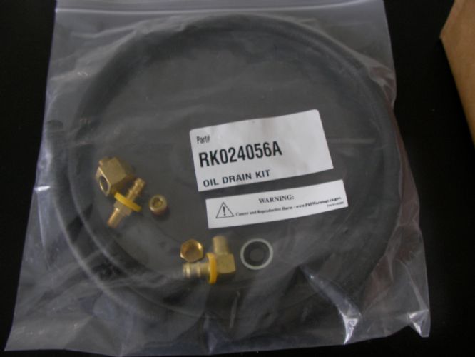 |
||
|
||
|
wayoutthere
Senior Member
Joined: February-28-2020 Location: Florida Status: Offline Points: 391 |
Post Options
Thanks(0)
Quote Reply
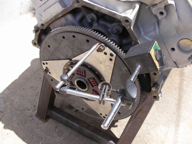
Posted: July-03-2021 at 5:11pm |
|
   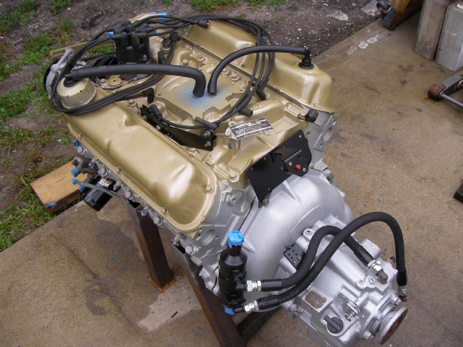 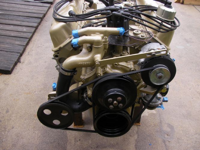 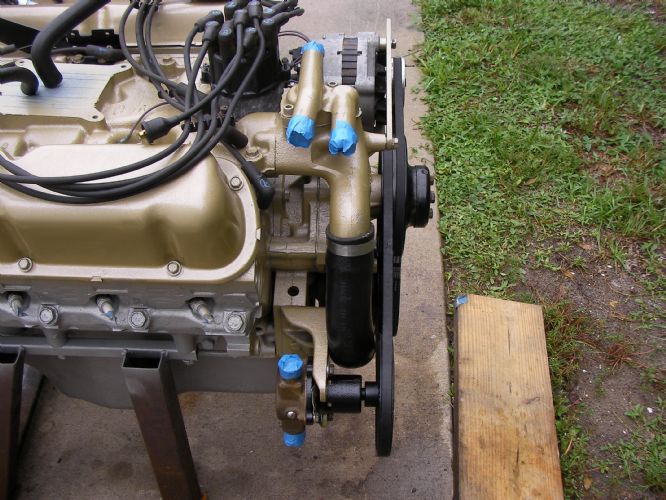 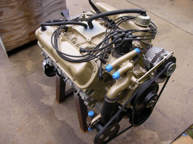 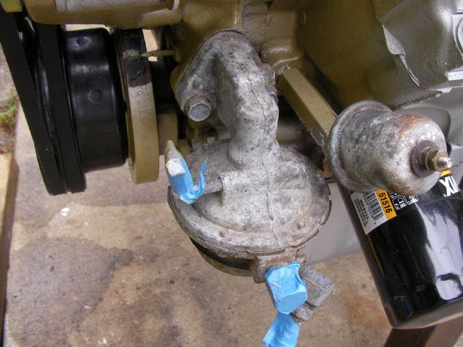 Got the flywheel back friday, got the dampener cut, then scribed it with the magnetic pointer and ground to finsh. Loctite and torqued thru the access hole in bell. Today, dressing the engine i had to stop and make bushings for the alternator and sea pump, there is no wear on their respective brackets or the accy's themselves, they just were not properly located and the belts were way off alignment. On/off on/off on/off took 6 hours to cut, fit, align the belts, paint the bushings and reassemble. Hoses had to be ordered, nothing in town that you'd want to pay for. Next off is the fuel pump, i don't know if there is any internal parts that will fall out or into the pan or if it's just the arm? Does the rotating assy have to be at a certain degree or tdc to correctly install it? Theres no clear info online and from memory the old mark4 454 had a rod that pushed the pump arm, have no idea how ford does it or how pcm may have changed it. Shooting for install next week.
|
||
|
||
|
wayoutthere
Senior Member
Joined: February-28-2020 Location: Florida Status: Offline Points: 391 |
Post Options
Thanks(0)
Quote Reply
Posted: July-03-2021 at 5:51pm |
|
|
The sea pump, i surfaced both halves and the wear plate with 1000 grit wet before installing the new kit.
Concern i have is the torque, my click type inch pounds starts at 20, from memory 14-16 inch pounds was what most pumps i've seen required. No info online, no instructions with kit. Think 20 inch pounds is too tight ?
|
||
|
||
|
KENO
Grand Poobah
Joined: June-06-2004 Location: United States Status: Offline Points: 10638 |
Post Options
Thanks(0)
Quote Reply
Posted: July-03-2021 at 5:55pm |
|
There aren't any parts that will fall out and like you said, there's just the arm on the pump The eccentric is mounted on the end of the cam and the arm is moved by the eccentric. Pretty much any engine position works, but you can find the position where the eccentric exerts the least pressure if you're having problems getting the pump into place against the spring pressure on the arm. Some people use a long stud or longer bolt to get one side started, then put the other bolt in, tighten it some and then take out the temporary bolt, put the original back in and tighten both sides incrementally. I'm kinda wimpy and I usually don't have a problem overcoming the spring pressure It's only hard the first time It's easier at least for me, than the Chevy pushrod setup Edit.......#1 at TDC on the compression stroke is maximum pressure on the arm, so putting #6 at TDC is the least pressure. so put#1 at TDC and rotate the crankshaft one full turn and you'll be in the right spot with #6 now at TDC.
|
||
|
||
|
KENO
Grand Poobah
Joined: June-06-2004 Location: United States Status: Offline Points: 10638 |
Post Options
Thanks(0)
Quote Reply
Posted: July-03-2021 at 6:32pm |
|
|
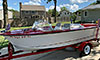
Here's a picture borrowed from somewhere on the internet showing the eccentric position when the engine is at TDC on the compression stroke on #1 and would be exerting max pressure on the arm. One turn of the crankshaft rotates the camshaft 1/2 turn to the minimum pressure position. 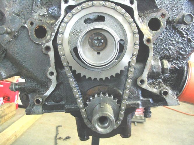 |
||
|
||
|
wayoutthere
Senior Member
Joined: February-28-2020 Location: Florida Status: Offline Points: 391 |
Post Options
Thanks(0)
Quote Reply
Posted: July-03-2021 at 7:11pm |
|
|
Thanks keno, that's huge help !
Sitting there looking at the engine it never dawned on me the pump is external, online i read about 1 piece eccentric that ford later changed to a 2 piece, that made me think something would fall out. Now knowing this and seeing that pic it will go a long way to building a mental picture of what needs to happen. I'll pull the plugs so the engine rolls over easier and pull the pump, maybe the bore scope can see the eccentric, that will go a long way towards cross checking tdc and eyeballing the timing mark and rotor position. Thanks, i'll get that pump ordered tonight. Happy 4th Edit in; should follow my advice, "get a manual" wonder if theres a chiltons 351w book
|
||
|
||
|
KENO
Grand Poobah
Joined: June-06-2004 Location: United States Status: Offline Points: 10638 |
Post Options
Thanks(0)
Quote Reply
Posted: July-03-2021 at 8:08pm |
|
|
||
|
wayoutthere
Senior Member
Joined: February-28-2020 Location: Florida Status: Offline Points: 391 |
Post Options
Thanks(0)
Quote Reply
Posted: July-09-2021 at 9:01pm |
|
 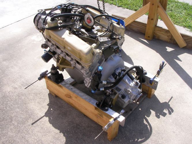       Engine in dummy stringers, set close for width, center and angle. Degrees as follows Pad 4 Strut port 2 Stringers 1 1/2 ( sitting in driveway, not levelled out to zero) Believe strut port should be same as pad, it was ground and shim was under rear of strut when disassembled. If pad was level 0, then strut port would be negative 2, add 3 for the shim, shaft angle was 18 degrees. There was a blob of bedding compound in the stern tube obstructing the shaft which threw the engine to port, plus there was 2 inches of spacing between the strut and prop. Way back i made a fiberglass shim for the rudder port to get the 2 degrees back and the old cutlass bearing will go into the stern tube when it gets bedded after alignment is achieved. Going to start alignment backwards; -front/back to get correct strut prop spacing - centerline the engine and set correct angle - grind fiberglass shim so strut is at 13, from there mount the strut and align engine, then bed stern tube. |
||
|
||
|
wayoutthere
Senior Member
Joined: February-28-2020 Location: Florida Status: Offline Points: 391 |
Post Options
Thanks(0)
Quote Reply
Posted: July-10-2021 at 3:40pm |
|
 
The engine landed 1/16 off center and 3/16 forward, moved the engine back and drilled 1 bolt hole in each corner. Got rained out out so finish drilling and sealing the holes tomorrow. I ground the shim and got the strut on @ 13 degrees, problem is the shaft won't go in the hole. Too late in the game to glass it shut and redrill.
|
||
|
||
|
gun-driver
Grand Poobah
Joined: July-18-2008 Location: Pittsburgh, Pa Status: Offline Points: 4112 |
Post Options
Thanks(0)
Quote Reply
Posted: July-10-2021 at 4:31pm |
|
|
How close was the prop to the strut?
Unless the prop is right against the strut (which is no good) I would think
with the coupler you would have been fine. |
||
|
||
|
KENO
Grand Poobah
Joined: June-06-2004 Location: United States Status: Offline Points: 10638 |
Post Options
Thanks(0)
Quote Reply
Posted: July-10-2021 at 8:08pm |
|
Don't know about the blob, but those era SN's had the 2 inch strut to prop clearance you mention from the factory, so if you changed that without changing shaft length, your engine will be in a quite a bit different spot than it originally was.
|
||
|
||
|
wayoutthere
Senior Member
Joined: February-28-2020 Location: Florida Status: Offline Points: 391 |
Post Options
Thanks(0)
Quote Reply
Posted: July-10-2021 at 8:46pm |
|
|
During the rebuild I mocked it up w/ 1/2 inch of prop/strut spacing and drilled 1 locating hole in the stringer.
That 3/16 i had to move the engine back was to keep that 1/2. The floor, stringers and dog box was all rebuilt around the engine placement. Now i have to put on the coupler and do an alignment in order to bed the stern tube.
|
||
|
||
|
KENO
Grand Poobah
Joined: June-06-2004 Location: United States Status: Offline Points: 10638 |
Post Options
Thanks(0)
Quote Reply
Posted: July-11-2021 at 5:53am |
|
|
I think that with all those degree numbers you're throwing around, only you know what you're talking about, but I think you know what you're doing..........so get that shaft in the hole
You gave a better description of the issue on PN
 |
||
|
||
|
wayoutthere
Senior Member
Joined: February-28-2020 Location: Florida Status: Offline Points: 391 |
Post Options
Thanks(0)
Quote Reply
Posted: July-11-2021 at 1:42pm |
|
|
The shaft is in but not at 13 degrees.
I throw the numbers out because over at pn one of the first replies was go to correccraftfan and ask technical questions. I've read alot of technical threads about these older boats and see the perfectly restored classics, i just figured you all have that math in your head and will chime in and guide me on this part like all the other help i was afforded thru this site.
Plus I post here first and by the time i get over to pn my fingertips are sore from poke typing Anyway to identify the strut, like to find out if its original or not? Is designed shaft angle of this boat supposed to be 13 ? There is 1 inch of clearance between hull and prop, prop is 13 dia. (I'll double check that dia) Rained out today, got all set up then clouds and thunder |
||
|
||
|
KENO
Grand Poobah
Joined: June-06-2004 Location: United States Status: Offline Points: 10638 |
Post Options
Thanks(0)
Quote Reply
Posted: July-11-2021 at 5:55pm |
|
|
A little diagram to go with the numbers would make things a lot easier to visualize.
The strut is listed by CC as a 154 DV, on nautiqueparts they call it a SA-154 They say it fits SN and Tique, CC in the chart doesn't agree with that 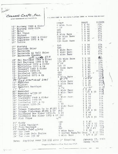 I don't think you'll find anybody doing the installation the same way as you are, but like I said, to me your way will work and work just fine. I bet you could do a 15 degree angle and line everything up pretty easily. I don't think 13 is what they used, think being the key word CC was known to shim a strut or 2
|
||
|
||
|
wayoutthere
Senior Member
Joined: February-28-2020 Location: Florida Status: Offline Points: 391 |
Post Options
Thanks(0)
Quote Reply
Posted: July-12-2021 at 5:20pm |
|
    
Engine angles to stringers, drilled - epoxy soaked - 4200 on both sides of the stingers, same for the ski pylon mount and steering knuckle. Waterpoof, don't know but piece of mind anyway. Thanks keno, i'll look for a number on the strut tomorrow.
|
||
|
||
|
KENO
Grand Poobah
Joined: June-06-2004 Location: United States Status: Offline Points: 10638 |
Post Options
Thanks(0)
Quote Reply
Posted: July-12-2021 at 5:41pm |
|
|
I don't think you'll find a number, but I'd use what you have and keep doing what you're doing
|
||
|
||
|
wayoutthere
Senior Member
Joined: February-28-2020 Location: Florida Status: Offline Points: 391 |
Post Options
Thanks(0)
Quote Reply
Posted: July-14-2021 at 7:16am |
|
|
I got a bent shaft !
|
||
|
||
|
ultrarunner
Platinum Member

Joined: October-02-2005 Location: Ridgefield, Ct. Status: Offline Points: 1809 |
Post Options
Thanks(0)
Quote Reply
Posted: July-14-2021 at 8:21am |
|
A competent machine shop can straighten it if not too far out, or call Elbert’s: http://www.elberts.com/system.htm |
||
|
||
|
wayoutthere
Senior Member
Joined: February-28-2020 Location: Florida Status: Offline Points: 391 |
Post Options
Thanks(0)
Quote Reply
Posted: July-14-2021 at 4:26pm |
|
Thank you, its out enough that it can be seen when rolled. Shaft wear at the cutlas bearing is enough to justify a new one, i was hoping to at least run the boat and see how it acted. |
||
|
||
|
wayoutthere
Senior Member
Joined: February-28-2020 Location: Florida Status: Offline Points: 391 |
Post Options
Thanks(0)
Quote Reply
Posted: July-14-2021 at 5:00pm |
|
    |
||
|
||
|
gun-driver
Grand Poobah
Joined: July-18-2008 Location: Pittsburgh, Pa Status: Offline Points: 4112 |
Post Options
Thanks(0)
Quote Reply
Posted: July-14-2021 at 9:24pm |
|
|
Get out the mig.

|
||
|
||
|
wayoutthere
Senior Member
Joined: February-28-2020 Location: Florida Status: Offline Points: 391 |
Post Options
Thanks(0)
Quote Reply
Posted: July-15-2021 at 1:22pm |
|
|
Believe that is stainless, 1 riser has/had different bolt material, i picked up 8 new bolts and an ez out.
It never reached 10 pnds torque. These manifolds are in good shape, i'll get it out and if it comes to it the tig will also reach. Might get to it over the weekend, truck is due for oil, lube, filters. brakes & shocks are here as well. |
||
|
||
|
wayoutthere
Senior Member
Joined: February-28-2020 Location: Florida Status: Offline Points: 391 |
Post Options
Thanks(0)
Quote Reply
Posted: July-22-2021 at 7:17pm |
|
|
Back on the boat as of today, not going to worry about broken riser bolt until wiring is complete.
Every diagram i have accounts for all wires except 1 the volt meter 2 the alternator 3 the circuit breaker 4 brown w/ blue tracer that is in the engine & boat harness but not the dash, it just hangs there. 2 versions of volt meter wiring and the mystery 10g that left the alt/dash side of the breaker but did not go to the dash has me thoroughly confused. The following wiring comes from 2 nautique schematics From I to battery w/ red
From S to alternator w/ orange From G to ground All wires 10 gauge The other way shows I purple, ground and light with no wire to the alternator. |
||
|
||
|
wayoutthere
Senior Member
Joined: February-28-2020 Location: Florida Status: Offline Points: 391 |
Post Options
Thanks(0)
Quote Reply
Posted: July-22-2021 at 7:35pm |
|

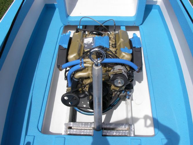
I see how purple and coil come from the dash, and the 10g red and black go off to the dash (center bottom of pic But the mystery red 10g wire leaving the alt/dash side of the breaker |
||
|
||
|
Post Reply
|
Page <1 23456 12> |
 Tweet
Tweet
|
| Forum Jump | Forum Permissions You cannot post new topics in this forum You cannot reply to topics in this forum You cannot delete your posts in this forum You cannot edit your posts in this forum You cannot create polls in this forum You cannot vote in polls in this forum |


 Topic Options
 KENO wrote: