 Boats For Sale:


Glass Layup Schedule on '82 2001? |
Post Reply 
|
Page <1 34567> |
| Author | |
Nautique Newby 
Groupie 
Joined: March-28-2017 Location: Alabama Status: Offline Points: 93 |
 Post Options Post Options
") Thanks(0) Thanks(0)
 Quote Reply Quote Reply
 Posted: November-03-2021 at 1:08pm Posted: November-03-2021 at 1:08pm |
|
[QUOTE=TRBenj]How far do you plan to trailer?
Sometimes could be as much as 90 miles each way. Most of the time less.
|
|
|
I hope I don't screw this up!
|
|
 |
|
|
Nautique Newby
Groupie
Joined: March-28-2017 Location: Alabama Status: Offline Points: 93 |
Post Options
Thanks(0)
Quote Reply
Posted: February-18-2022 at 10:11am |
|
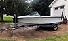
After five long years I'm finally ready for carpet. What's the record for longest stringer job on this site?
 I think the end is finally in site and she can get back in the water again this spring. (Sorry for the sideways pics, cant figure out how to rotate them)   |
|
|
I hope I don't screw this up!
|
|
|
|
|
JoeinNY
Grand Poobah 

Joined: October-19-2005 Location: United States Status: Offline Points: 5693 |
Post Options
Thanks(0)
Quote Reply
Posted: February-18-2022 at 11:33am |
|
Congratulations- she is looking great!
|
|
|
|
|
MechGaT
Senior Member 

Joined: March-09-2015 Location: Chattanooga Status: Offline Points: 271 |
Post Options
Thanks(0)
Quote Reply
Posted: February-18-2022 at 2:03pm |
|
Looks awesome. It will feel so great taking her out for the first cruise.
|
|
|
'92 Sport Nautique
|
|
|
|
|
Gary S
Grand Poobah

Joined: November-30-2006 Location: Illinois Status: Offline Points: 14096 |
Post Options
Thanks(0)
Quote Reply
Posted: February-18-2022 at 2:11pm |
|
+1 Your definitely in the home stretch now,with it being February you could finish it for this summer easily.
Winner and undisputed World Champion with a 10-0 record is john b and his Mustang Now that this covid thing is hopefully over I'll have to check up on him and see how he's doing.
|
|
|
|
|
Nautique Newby
Groupie
Joined: March-28-2017 Location: Alabama Status: Offline Points: 93 |
Post Options
Thanks(0)
Quote Reply
Posted: February-18-2022 at 2:53pm |
|
"Winner and undisputed World Champion with a 10-0 record is john b and his Mustang "
 Wow! 10 years and counting. I guess my 5 year journey isn't so bad after all. Wow! 10 years and counting. I guess my 5 year journey isn't so bad after all. |
|
|
I hope I don't screw this up!
|
|
|
|
|
67 ski nat
Platinum Member 
Joined: July-19-2018 Location: Santa rosa Status: Offline Points: 1180 |
Post Options
Thanks(0)
Quote Reply
Posted: February-19-2022 at 10:36am |
|
Nice looking job.
Did you put foam back |
|
|
|
|
67 ski nat
Platinum Member
Joined: July-19-2018 Location: Santa rosa Status: Offline Points: 1180 |
Post Options
Thanks(0)
Quote Reply
Posted: February-20-2022 at 1:57pm |
|
Wow. I enlarged picture. Really like the running hardware plumbing too
You’ve been quietly building a great boat |
|
|
|
|
Nautique Newby
Groupie
Joined: March-28-2017 Location: Alabama Status: Offline Points: 93 |
Post Options
Thanks(0)
Quote Reply
Posted: February-20-2022 at 10:30pm |
|
Thanks for the compliments. Yes I decided to put the foam back in the floor. To help minimize water intrusion I eliminated as many fiberglass penetrations as possible. I will attached the seats to the teak (epoxied to the floor) instead of screwing through the fiberglass. Same for the wire supports in the bilge.
Got the sides carpeted this weekend. Hopefully will have the floors done before the week is out.
|
|
|
I hope I don't screw this up!
|
|
|
|
|
Timr71
Groupie
Joined: March-28-2016 Location: Alabama Status: Offline Points: 80 |
Post Options
Thanks(0)
Quote Reply
Posted: February-22-2022 at 6:03pm |
|
Wow! super excited to find this thread...again. Great work. You'll be back on the lake this spring/summer.
|
|
|
|
|
Nautique Newby
Groupie
Joined: March-28-2017 Location: Alabama Status: Offline Points: 93 |
Post Options
Thanks(0)
Quote Reply
Posted: March-25-2022 at 9:57am |
|
I've installed all of the carpet. Just need the vinyl trim pieces at the edge of rear plywood floor over the bilge. And vacuum it real well and clean up a bit. Again, sorry for the rotated pics.
  |
|
|
I hope I don't screw this up!
|
|
|
|
|
Nautique Newby
Groupie
Joined: March-28-2017 Location: Alabama Status: Offline Points: 93 |
Post Options
Thanks(0)
Quote Reply
Posted: April-13-2022 at 11:14am |
|
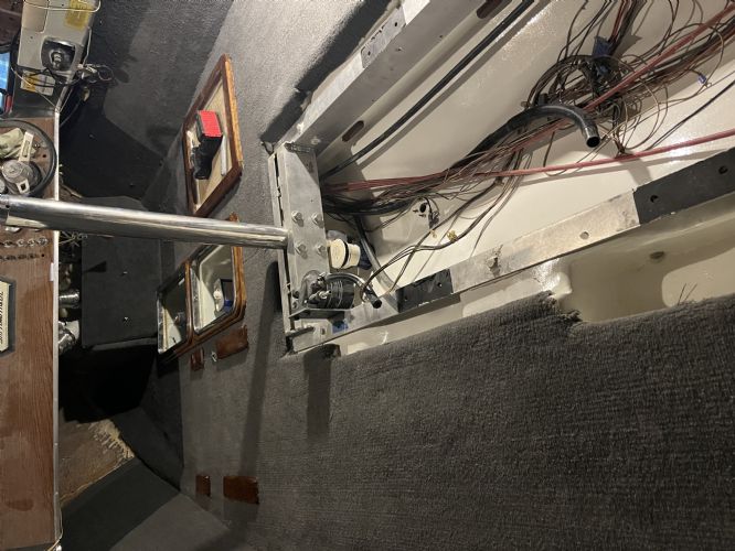
The wiring on my 351W PCM engine is a mess. There are numerous wire splices (one wire changed color 3 time from the engine harness to the oil sending unit) and some wires are bare. Others are abandoned and just hanging loose.
Therefore I'm cleaning all of it up by rewiring and replacing the engine harness all the way to the dash. I've got a wiring diagram of this engine but the diagram does not include the device circled in blue on in this pic. I also cannot find it on the parts list at Nautique Parts website, which seems to carry most all the replacement parts. Does anyone know what this device is? This engine was changed to EI at some point (which I'm also replacing since it's junk) so I thought it may be part of that.  |
|
|
I hope I don't screw this up!
|
|
|
|
|
andrewmarani
Senior Member
Joined: May-31-2005 Location: Baltimore, MD Status: Offline Points: 210 |
Post Options
Thanks(0)
Quote Reply
Posted: April-13-2022 at 11:40am |
|
Is it on the back of the engine? Is it a plastic cover that you can remove with one screw? On mine, it covers the solenoid, the resistor and the battery cable hookups to the solenoid. Maybe back up the camera and take another picture so we can see it's location on the engine better.
|
|
|
Builder
|
|
|
|
|
Nautique Newby
Groupie
Joined: March-28-2017 Location: Alabama Status: Offline Points: 93 |
Post Options
Thanks(0)
Quote Reply
Posted: April-13-2022 at 11:50am |
|
Yes it's on the back of the engine. Any plastic cover that may have been on it originally (covering the breaker and solenoid) is long gone before I bought it. I've attached another pic for context. The starter solenoid is on the right. the 40amp breaker is in the center (behind the harness). The part in question is on the left in blue. The device itself is a silver (alum?) metal box.
 |
|
|
I hope I don't screw this up!
|
|
|
|
|
andrewmarani
Senior Member
Joined: May-31-2005 Location: Baltimore, MD Status: Offline Points: 210 |
Post Options
Thanks(0)
Quote Reply
Posted: April-13-2022 at 11:52am |
|
Never mind, I see that stuff on the right of the picture. Looking at a picture of the back of my engine, also a 351, from 1986, I don't see whatever that is. Does it look like an added item or original to the engine?
And yeah that wiring looks a mess. Make sure you run a heavier positive and ground from the block under the dash to the engine, they were undersized when built. If you decide to rewire the dash, also messed up when built, I can send before and after pictures of mine. Worked out well and isn't that hard if you pull the dash and work on it in the kitchen in the evening, while discussing life with your very patient wife.
|
|
|
Builder
|
|
|
|
|
andrewmarani
Senior Member
Joined: May-31-2005 Location: Baltimore, MD Status: Offline Points: 210 |
Post Options
Thanks(0)
Quote Reply
Posted: April-13-2022 at 12:03pm |
|
Been awhile since I posted a picture. If the picture shows up, I don't see anything like that on my engine. Heavy black and red wires on the right are new, run from the block under the dash that I mentioned.
|
|
|
Builder
|
|
|
|
|
Nautique Newby
Groupie
Joined: March-28-2017 Location: Alabama Status: Offline Points: 93 |
Post Options
Thanks(0)
Quote Reply
Posted: April-13-2022 at 12:09pm |
|
I can't really tell if it was aftermarket add. I'm starting to think it's an external voltage regulator. Most of the wires go to the alternator.
What gage red and black (and orange) did you use from dash to the engine? The new harness I got has the same 10ga that was original. That's what I got to replace it. Right now I'm just trying to rewire from engine to the wire harness under the dash. Yes the dash is a mess too but I'm going to try and wait on that rabbit hole until after summer. I would definitely be interested in your pics. |
|
|
I hope I don't screw this up!
|
|
|
|
|
andrewmarani
Senior Member
Joined: May-31-2005 Location: Baltimore, MD Status: Offline Points: 210 |
Post Options
Thanks(0)
Quote Reply
Posted: April-13-2022 at 12:13pm |

|
|
|
Builder
|
|
|
|
|
TRBenj
Grand Poobah

Joined: June-29-2005 Location: NWCT Status: Offline Points: 21107 |
Post Options
Thanks(0)
Quote Reply
Posted: April-13-2022 at 12:16pm |
|
External voltage regulator is correct, it appears original. Pcm went to internally regulated in ~83.
|
|
|
|
|
andrewmarani
Senior Member
Joined: May-31-2005 Location: Baltimore, MD Status: Offline Points: 210 |
Post Options
Thanks(0)
Quote Reply
Posted: April-13-2022 at 12:17pm |
|
These are in addition to the original wire harness, which still exists. I don't remember the gauge but 10 sounds plenty big for the load. Wires I'm referring to are actually in the top middle of the picture. They have the black zip tie holding them together at one spot.
|
|
|
Builder
|
|
|
|
|
KENO
Grand Poobah
Joined: June-06-2004 Location: United States Status: Offline Points: 10641 |
Post Options
Thanks(0)
Quote Reply
Posted: April-13-2022 at 12:25pm |
|
Nautique Newby's 82 was built with an externally regulated alternator and Andrew, your 86 had an internally regulated alternator so you won't find that regulator on yours..
Are you working from a wiring diagram or just wingin' it?
Edit Sounds like I just said what TRB said in slightly different words.
 |
|
|
|
|
Nautique Newby
Groupie
Joined: March-28-2017 Location: Alabama Status: Offline Points: 93 |
Post Options
Thanks(0)
Quote Reply
Posted: April-13-2022 at 12:33pm |
|
I'd very much like to work from a diagram but apparently I don't have an '82 since the voltage regulator is not on it. If anyone has one and would like to share I would very much appreciate it.
 Most of it is just replacing like for like and cleaning up dirty/corroded contacts. But some of the loose wires do need to come out so the diagram would be helpful.
|
|
|
I hope I don't screw this up!
|
|
|
|
|
KENO
Grand Poobah
Joined: June-06-2004 Location: United States Status: Offline Points: 10641 |
Post Options
Thanks(0)
Quote Reply
Posted: April-14-2022 at 7:39am |
|
I guess I'm confused, is the picture with the blue circled regulator some other engine than yours since you say you don't have the regulator?
Somebody may have replaced the alternator with an internally regulated one in the past and ditched the external one since it wouldn't be needed. And that would lead to some unused wires and maybe contribute to the wiring mess. How about a picture of your alternator? Just to help get a diagram that's at least as close as possible, do you have an ammeter on the dash and not a voltmeter?
|
|
|
|
|
Nautique Newby
Groupie
Joined: March-28-2017 Location: Alabama Status: Offline Points: 93 |
Post Options
Thanks(0)
Quote Reply
Posted: April-14-2022 at 2:44pm |
|
Andrew's boat does not have the voltage regulator because it's a later model than mine. Mine does (pic with blue circle).
All the wires on my voltage regulator go to the alternator except the purple ignition wire, which is loose. I'm fairly certain my dash gage is a voltmeter but I'll need to double check. Also looks like I need to replace the neutral switch on the velvet drive. The two wires are on the same contact so I'm assuming the switch is bad and previous owner bypassed it. Luckily that part is inexpensive. I'm slowly creating a brand new boat... piece by piece
|
|
|
I hope I don't screw this up!
|
|
|
|
|
andrewmarani
Senior Member
Joined: May-31-2005 Location: Baltimore, MD Status: Offline Points: 210 |
Post Options
Thanks(0)
Quote Reply
Posted: April-14-2022 at 2:59pm |
|
Not sure how much time you've put into the neutral switch at this point but... I had a neutral switch issue, (nothing happened when I turned the key occasionally) spent time chasing it around. Turned out i needed to adjust the center stop on the shift cable. Just two turns of the nut on the end of the cable at the velvet drive and issue solved. very easy, only took me a month to figure it out.
|
|
|
Builder
|
|
|
|
|
Nautique Newby
Groupie
Joined: March-28-2017 Location: Alabama Status: Offline Points: 93 |
Post Options
Thanks(0)
Quote Reply
Posted: April-14-2022 at 3:06pm |
|
Thanks Andrew. At this point I haven't invested any time. I'm just assuming the safety switch is bad since the wires on are on the same contact. I probably wont do anything with it yet until I can test it in the water. I do know I will need to adjust the cable/mount because the last time I used it the shaft would turn very slowly when I shifted to neutral. If I then shifted to reverse and back to neutral it would stop. Assuming it's an adjustment issue.
|
|
|
I hope I don't screw this up!
|
|
|
|
|
KENO
Grand Poobah
Joined: June-06-2004 Location: United States Status: Offline Points: 10641 |
Post Options
Thanks(0)
Quote Reply
Posted: April-14-2022 at 5:48pm |
So you must mean you have a diagram that's not an 82. Now I get it Once you post whether you have an ammeter or voltmeter, a diagram might come along.  If you want to test the Neutral Safety switch, take both wires off the switch, disconnect your shift cable from the transmission and put the transmission in neutral using the shift lever on the transmission............then using an ohmmeter, check that you have continuity (something near zero ohms) Continuity means it's good and no continuity means it's bad. There's no adjustment of the switch itself, just the cable and no matter how you adjust the cable a bad switch is a bad switch. Your spinning shaft in neutral sounds like a slightly dirty neutral that most likely won't be an adjustment issue, Lots of people live with a dirty neutral unless it gets too bad. |
|
|
|
|
Nautique Newby
Groupie
Joined: March-28-2017 Location: Alabama Status: Offline Points: 93 |
Post Options
Thanks(0)
Quote Reply
Posted: April-15-2022 at 9:33am |
|
Gage is volts.
Thanks for the help!
|
|
|
I hope I don't screw this up!
|
|
|
|
|
KENO
Grand Poobah
Joined: June-06-2004 Location: United States Status: Offline Points: 10641 |
Post Options
Thanks(0)
Quote Reply
Posted: April-15-2022 at 7:19pm |
|
Here's a wiring diagram that PCM used in the early 70's when they were a division of Waukesha. It's pretty good for engines up till the 83/84 timeframe when they started using an internally regulated alternator. I put circles around areas that you'll find different. In the orange circle at the top it shows a dotted line and says "clip this wire if ammeter is used. Since you have a voltmeter that line isn't clipped and goes to the starter solenoid through your 40 amp breaker and the line going to the dash for the ammeter is clipped off and taped and the ammeter and Red wire in the blue circle don't exist. The Yellow circle is where your Neutral Safety Switch would be wired in. The Green circle is an Idiot light that you don't have and the Purple circle is a rev limiter that you don't have. The dash section doesn't show the fuses that are on your dash and doesn't show everything that's on the dash. It's probably as good as you'll get for a diagram that's representative of your 82  I'll guess that you're using the diagram below which works good for 83/84 ish up until the late 90's for carbureted 351 PCM's.with a distributor It's a homegrown diagram by TRBenj that get posted by different people all over the internet whether it really pertains or not.  If you need the voltage regulator you're asking about, it wouldn't be that hard or expensive to get an internally regulated replacement for the Mando internally regulated alternator used in the later 80's and wire your engine per the TRB diagram that's a whole lot easier to follow Hopefully this helps with your wiring cleanup job and doesn't just confuse you more There's also a dash diagram floating around that shows wiring for a dash with an ammeter that maybe you've seen
|
|
|
|
|
Nautique Newby
Groupie
Joined: March-28-2017 Location: Alabama Status: Offline Points: 93 |
Post Options
Thanks(0)
Quote Reply
Posted: April-18-2022 at 7:31am |
|
Thank you Keno. This will be helpful!
|
|
|
I hope I don't screw this up!
|
|
|
|
|
Post Reply
|
Page <1 34567> |
 Tweet
Tweet
|
| Forum Jump | Forum Permissions You cannot post new topics in this forum You cannot reply to topics in this forum You cannot delete your posts in this forum You cannot edit your posts in this forum You cannot create polls in this forum You cannot vote in polls in this forum |


 Topic Options
 Nautique Newby wrote: