 Boats For Sale:


Removing Protec & Throttlebody, installing carb |
Post Reply 
|
Page 123 4> |
| Author | |
Erikgundy98 
Groupie 
Joined: February-09-2021 Location: Vancouver, wa Status: Offline Points: 62 |
 Post Options Post Options
") Thanks(0) Thanks(0)
 Quote Reply Quote Reply
 Topic: Removing Protec & Throttlebody, installing carb Topic: Removing Protec & Throttlebody, installing carbPosted: April-13-2021 at 6:19pm |
|
I am installing the distributor, after removing the old wiring harness, and am stuck on how to find TDC when I dont actually have a distributor currently installed (the ProTec ignition is almost all uninstalled, but the instructions on the new (Nautique Parts) instructions for moving from Protec to Distributor says to set engine to TDC.
Do you have a strategy to do so without removing the valve cover to look at the valves? Thanks! Erik |
|
 |
|
|
8122pbrainard
Grand Poobah 

Joined: September-14-2006 Location: Three Lakes Wi. Status: Offline Points: 41040 |
Post Options
Thanks(1)
Quote Reply
Posted: April-13-2021 at 6:45pm |
|
Place your thumb over the #1 cylinder spark plug hole, crank the engine over and when the compression stops you'll be close.
|
|
|
|
|
KENO
Grand Poobah
Joined: June-06-2004 Location: United States Status: Offline Points: 10641 |
Post Options
Thanks(1)
Quote Reply
Posted: April-13-2021 at 7:42pm |
|
What's that old saying about "close is only good enough in horseshoes and hand grenades" ?
Assuming that you can see the timing marks on your harmonic balancer, you'll need a ratchet wrench, a short extension and a 15/16 socket to fit the bolt holding the balancer to the crankshaft, so you can turn the engine in the normal direction of rotation.(in your case, clockwise while you're looking at it from the front) If you take all the plugs out, it will be a lot easier to turn the engine over (and you can check their condition at the same time) Then you turn the engine with the wrench and put a thumb over the #1 spark plug hole and eventually you'll feel some pressure building up against your thumb. While this is happening, look at the timing pointer and the timing marks on the balancer As the pressure continues to build, you'll see the TDC mark on the balancer line up with the pointer and you're now at TDC on the compression stroke.. Now that you're at TDC on the compression stroke, you can install the distributor
 |
|
|
|
|
TRBenj
Grand Poobah

Joined: June-29-2005 Location: NWCT Status: Offline Points: 21107 |
Post Options
Thanks(0)
Quote Reply
Posted: April-13-2021 at 7:43pm |
|
One usually lines up the TDC mark (0°) on the balancer with the timing pointer.
As Pete implied, you’ll want to set it to TDC on the compression stroke, which can be found as he describes (plus lining up the aforementioned timing marks). Dammit KenO |
|
|
|
|
KENO
Grand Poobah
Joined: June-06-2004 Location: United States Status: Offline Points: 10641 |
Post Options
Thanks(0)
Quote Reply
Posted: April-13-2021 at 7:48pm |
Damn what? I guess we both figured that somebody had to clear up Pete's info a little bit |
|
|
|
|
Erikgundy98
Groupie
Joined: February-09-2021 Location: Vancouver, wa Status: Offline Points: 62 |
Post Options
Thanks(0)
Quote Reply
Posted: April-13-2021 at 7:48pm |
|
I feel so stupid. Thanks for the advice! Worked perfect. I was holding my finger over #5, which has good pressure too (not that it matters), but I was so confused why the balancer (didnt know the name of that) with the timing pointer. Once I found that I was on the wrong side of the engine, when I found pressure building on #1, sure enough the pointer was right at T/C on the timing marks.
Thanks guys! I hate asking stupid questions, but after everything I was reading said to "find TDC" and it has been a few years since I have had to time my Vanagon, thus a few years since I have read my manual and really gotten into an engine :) I really appreciate the help. On to putting in the distributor... :) Erik |
|
|
|
|
KENO
Grand Poobah
Joined: June-06-2004 Location: United States Status: Offline Points: 10641 |
Post Options
Thanks(0)
Quote Reply
Posted: April-13-2021 at 7:56pm |
|
You must be swapping to a carburetor with their kit too?
|
|
|
|
|
Erikgundy98
Groupie
Joined: February-09-2021 Location: Vancouver, wa Status: Offline Points: 62 |
Post Options
Thanks(0)
Quote Reply
Posted: April-13-2021 at 8:29pm |
|
Yes I am. I’m about to go look at the stickeys to see if there is a good write up on this. I saw some before I started, but not many with great picture. It’s the little things I don’t want to mess up.
|
|
|
|
|
KENO
Grand Poobah
Joined: June-06-2004 Location: United States Status: Offline Points: 10641 |
Post Options
Thanks(0)
Quote Reply
Posted: April-14-2021 at 7:50am |
|
From another thread, it sounds like you're having issues with the retro fit kit wiring and the instructions.
The kit you bought comes with a complete engine side wiring harness to replace what's there now (or at least it should have). Are the instructions hand scribbled on a dirty napkin or maybe something a little better? You must have a diagram or instructions for hooking up the Mallory MBI distributor and ballast resistor that comes in the kit I assume. The fuel side consists of removing the throttle body, installing the carburetor along with a mechanical fuel pump and new fuel line to the carburetor from the pump. It'd be good to check the fuel line from the tank to the pump too, if it's the original. There never has been much of a writeup on the carb swap that I can remember and lots of pictures have disappeared from CCF due to "issues" last summer. If you need some directions or a diagram for the ignition side of things, something could be posted
|
|
|
|
|
Erikgundy98
Groupie
Joined: February-09-2021 Location: Vancouver, wa Status: Offline Points: 62 |
Post Options
Thanks(0)
Quote Reply
Posted: April-14-2021 at 6:25pm |
|
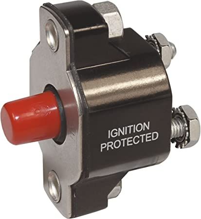
Thanks! I am doing just what you said. I am stuck on the list where it says “•TRANSFER STARTER RELAY (I can do this) AND CIRCUIT BREAKER TO NEW BRACKET ...”
I don’t know what circuit breaker they are talking about. Thanks for the help! I got TDC... ready to install wires, but I guess I will start with the wiring harness and see what is needed from the old stuff... I’ll probably figure out this “circuit breaker”... but it’s got me stumped |
|
|
|
|
8122pbrainard
Grand Poobah
Joined: September-14-2006 Location: Three Lakes Wi. Status: Offline Points: 41040 |
Post Options
Thanks(0)
Quote Reply
Posted: April-14-2021 at 6:44pm |
|
|
|
|
|
Erikgundy98
Groupie
Joined: February-09-2021 Location: Vancouver, wa Status: Offline Points: 62 |
Post Options
Thanks(0)
Quote Reply
Posted: April-14-2021 at 7:00pm |
|
There are 3 of those on mine. I imagined they were for remote starting... but 3?
Thanks. Did you (would you) transfer all 3? |
|
|
|
|
8122pbrainard
Grand Poobah
Joined: September-14-2006 Location: Three Lakes Wi. Status: Offline Points: 41040 |
Post Options
Thanks(0)
Quote Reply
Posted: April-14-2021 at 7:34pm |
|
Erik,
Didn't you get any wiring diagram with it? Here's Tim's that may help.: 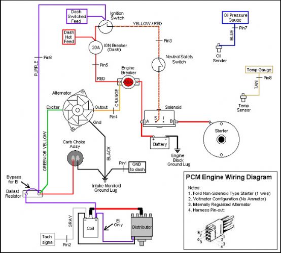 |
|
|
|
|
KENO
Grand Poobah
Joined: June-06-2004 Location: United States Status: Offline Points: 10641 |
Post Options
Thanks(0)
Quote Reply
Posted: April-14-2021 at 7:50pm |
The only breaker of the 3 that you keep is the 50 amp breaker for the conversion. The other 2 go into your "spare parts" collection. If you go to the thread in the link below, when you get to the last post, there is a good explanation of the wiring. And here's a slightly different diagram than what Pete posted, it's been corrected to show how the choke, ballast resistor supply and alternator excitation are connected under the tape in the harness and not at the ballast resistor. It also shows the correct wiring for the solenoid and the starter assuming you have a PMGR starter which PCM started using in 93 You'll have to figure out how to enlarge it and rotate it or print it and enlarge it.  If you combine the linked thread and the picture, things will make a lot more sense.  PS If anybody is wondering about the changes to the TRB diagram, they're based on a completely untaped wiring harness I have hanging on the wall. The TRB diagram gets the point across, but the connections are buried in the harness and you'll get confused just like the guy on Planet Nautique in the linked thread
|
|
|
|
|
KENO
Grand Poobah
Joined: June-06-2004 Location: United States Status: Offline Points: 10641 |
Post Options
Thanks(0)
Quote Reply
Posted: April-14-2021 at 8:19pm |
|
And this probably came with the kit, but if not, it's how the Mallory MBI distributor in your kit is wired
 |
|
|
|
|
Erikgundy98
Groupie
Joined: February-09-2021 Location: Vancouver, wa Status: Offline Points: 62 |
Post Options
Thanks(0)
Quote Reply
Posted: April-15-2021 at 1:03am |
|
The distributor absolutely did not come with a picture like this. Thank you for this! Thanks for all the links and advice. My wiring harness (from Nautique Parts) is daunting, and I am worried that there are way more wires I took off, than this new one has that I am putting back on. And while there was a diagram (similar to the color one you included above), it was a copy of a copy of a copy, and NP said it is all they have. So thank you a lot for your "Much better" drawings. I really appreciate yours!
So, I just took off the throttle body, but is the riser (1" thick riser that the breather tube from the port valvecover attaches to, and was under the throttlebody), is this part of the throttle body, and thus gets removed? Or does it remain, and the new carburetor goes on top of the 1" ... it looks like the new carburetor could go on this, or straight on the engine without it? These are the little things I just dont know, that I dont want to make mistakes leaving behind, when it should be removed. The studs look like if I removed the riser, the studs would be much too long for the carburetor, but I am just not sure.
Thanks for the above links, pictures and advice. And thanks again in advance. Erik |
|
|
|
|
KENO
Grand Poobah
Joined: June-06-2004 Location: United States Status: Offline Points: 10641 |
Post Options
Thanks(0)
Quote Reply
Posted: April-15-2021 at 6:41am |
|
Thank TRBenj for the wiring diagram, I just modified it a little to show how the wires hook together inside the harness.
In your case it makes things easier.If you look at the colors on the diagram and the colors of the wires in the harness, you'll know for example that the light Blue wire goes to the oil pressure sending unit,Tan goes to the water temperature sending unit, Orange is the output from the alternator to the 50 amp breaker that you're reusing. Just label each temporarily and it'll be easier to get it all wired right. Pay attention to the pin numbers for the 8 plug connector also to help figure things out. You have extra wires on the harness you removed because it was more complicated with the Protec and throttle body. People who have replaced the protec with a DUI distributor and didn't get a kit with a new harness, have usually cut and taped over the extra wires and had to add things like a wire for power to the choke.. Your new harness works and is easier. The spacer should stay in place, it gives a spot for the PCV hose to hook into. Some carburetors will have a spot for the hose to hook into and some don't. Even if your carburetor has a spot for the hose, keep the spacer and cap the extra hose connection, otherwise you'll have a giant vacuum leak.
|
|
|
|
|
KENO
Grand Poobah
Joined: June-06-2004 Location: United States Status: Offline Points: 10641 |
Post Options
Thanks(0)
Quote Reply
Posted: April-15-2021 at 6:50am |
|
The distributor wiring schematic came from the link below for the same kit you bought.
link
I guess they don't make a copy of a copy of a copy, they give you a nice clear easy to read picture The TRBenj diagram was "home grown" here on CCF and gets referenced a lot cuz it good and easy to follow. There are a couple different versions of it. It shows up on a lot of different websites and in printed versions stuffed into somebody's toolbox etc. |
|
|
|
|
Erikgundy98
Groupie
Joined: February-09-2021 Location: Vancouver, wa Status: Offline Points: 62 |
Post Options
Thanks(0)
Quote Reply
Posted: April-18-2021 at 2:07am |
|
This definitely didn’t come with my kit. Wish it did.
Thanks for this. I’ll be working on it tomorrow. I installed the carburetor yesterday, but getting the new mechanical fuel pump in is a real chore. Since there is pressure on the lever, even after turning the engine to a position where it was at its minimal pressure, in order to line up the bolt holes, it’s one heck of a feat to get. Any advice? I thought about studs and nuts as the studs can be in first which could help with alignment. Or have I not turned the engine enough to get to a location where the lever on the manual fuel pump is not under pressure? Also, does anyone have a picture of the return fuel line / top of engine? I don’t know where the return fuel line (to tank) now attaches. Thanks again! Erik |
|
|
|
|
KENO
Grand Poobah
Joined: June-06-2004 Location: United States Status: Offline Points: 10641 |
Post Options
Thanks(0)
Quote Reply
Posted: April-18-2021 at 10:06am |
|
How long are the bolts that you're using?
Since you're replacing a blocking plate that's a lot thinner than a fuel pump, if you're using the original bolts they're too short to make your life easy The bolts should be 1 1/2 inches and with a lockwasher under the head, that leaves enough bolt length to get a good push on the pump with one hand and get one bolt started, then go to the other bolt, get it started and then tighten evenly a little on both bolts till the pump is tightened down. You could use a stud or longer bolt for the first bolt to make it easier and then put in the right length bolt in the end. Some people have used studs and left them installed. It like a lot of other things.............it's not too hard to do after the first time you do it (but the first time can be a killer) If the engine is rotated 1 full turn past TDC on #1 it's a lot easier to install (least amount of pressure on the arm)
|
|
|
|
|
KENO
Grand Poobah
Joined: June-06-2004 Location: United States Status: Offline Points: 10641 |
Post Options
Thanks(0)
Quote Reply
Posted: April-18-2021 at 10:09am |
Do you mean, "what do you do with the old fuel return line from the throttle body?" Or do you mean "where do you hook the hose from the 1/4 inch tubing fitting on the fuel pump to?"
|
|
|
|
|
Jonny Quest
Grand Poobah

Joined: August-20-2013 Location: Utah--via Texas Status: Offline Points: 2840 |
Post Options
Thanks(0)
Quote Reply
Posted: April-18-2021 at 10:22am |
|
Erik:
The ProTec with throttle-body fuel injection used an electronic fuel pump with a return fuel line to the tank. That return line is no longer needed with a mechanical fuel pump. When I did the ProTec-to-carburetor conversion, I cut the return fuel line near the tank and then inserted a plug and used a hose clamp to ensure a good seal. Installing mechanical fuel pump -- yes, getting the actuator arm to "seat" in position can be a p-i-t-a at times. Rotating the engine in small increments may enable you to engage the actuator arm a bit easier. Take out the spark plugs and put a large socket on the harmonic balancer up front. Then, using a breaker bar or large ratchet, you can turn the engine to find the "sweet spot" for installation. The threaded stud option may also help. Try using just 1 threaded stud as a guide and to hold the pump while you install the bolt in the other side. Then you can remove the stud and install the other bolt. JQ
|
|
|
Current
2003 Ski Nautique 206 Limited Previous 2001 Ski Nautique Open Bow 1994 Ski Nautique Open Bow Aqua skiing, ergo sum |
|
|
|
|
Erikgundy98
Groupie
Joined: February-09-2021 Location: Vancouver, wa Status: Offline Points: 62 |
Post Options
Thanks(0)
Quote Reply
Posted: April-18-2021 at 10:45am |
|
Sorry, yes I see how to connect the fuel line into the carb from the new mechanical fuel pump, but on the throttle body, the fuel in, and return line to the fuel tank were right next to each other (formed hard lines). I know the line from the old fuel pump is now to be removed, but not sure what to do about that 2nd line.
Assuming both old hard lines get deleted, but where on the carb (if at all) does a 2nd line (return line I assume) get connected? I notice on fuel injected cars, I have this return fuel line to the tank. But in a different life (before kids), on my old vw’s Pict 34 carburetor (70 Ghia, 71 westy, 74 bug) I don’t remember the presence of this return line. How does the throttlebody to carb conversion deal with this? Thank you again for your advice, knowledge, and insight! |
|
|
|
|
Erikgundy98
Groupie
Joined: February-09-2021 Location: Vancouver, wa Status: Offline Points: 62 |
Post Options
Thanks(0)
Quote Reply
Posted: April-18-2021 at 10:51am |
|
Ha! Thanks for the fuel line advice! I wondered! I didn’t think it was going to connect.
That fuel pump is my nemesis right now! Glad to see it’s not just me. Im so glad to have you guys. Once I’m done with this, I’ll definitely offer advice like you all are :) Did you all add gasket sealer to either the carb or fuel pump gasket? I saw a guy on YouTube add it when I was searching for “how to get that PITA fuel pump” on. But i never did on my old carbs nor fuel pump on the vw’s. Thanks! |
|
|
|
|
Jonny Quest
Grand Poobah
Joined: August-20-2013 Location: Utah--via Texas Status: Offline Points: 2840 |
Post Options
Thanks(0)
Quote Reply
Posted: April-18-2021 at 12:09pm |
|
I used a carb sealing plate and good quality gaskets. No gasket sealer for me.
Carb sealing plate from Jegs - Part Number: 555-15442 QuickFuel carb gaskets - Part Number 8-102QFT for open style and Part Number 8-1105QFT for the 4-hole style
JQ
|
|
|
Current
2003 Ski Nautique 206 Limited Previous 2001 Ski Nautique Open Bow 1994 Ski Nautique Open Bow Aqua skiing, ergo sum |
|
|
|
|
KENO
Grand Poobah
Joined: June-06-2004 Location: United States Status: Offline Points: 10641 |
Post Options
Thanks(0)
Quote Reply
Posted: April-18-2021 at 1:59pm |
|
Here's a picture of a Carter marine fuel pump and a Holley carburetor. Along with hooking up whatever you decide to use for a fuel line from the pump to the carburetor, you also should be running a piece of clear tubing between the nipple on the fuel pump and the nipple on the carburetor. In the picture they both have a Red cap to show where they are. That line is so that if your fuel pump diaphragm cracks and fails, fuel will be visible in that line and it will be dumping into the carburetor instead of the bilge. It'll make the engine run like crap or stall due to being flooded, but it's safer than blowing yourself up. Older Holley's don't have that nipple and you run the hose to a nipple like that on the flame arrestor. Your flame arrestor on a ProTec engine doesn't have that nipple but one can be added or you can get another flame arrestor with the nipple fitting. Not knowing what your Holley has, I figured I'd throw that info out there. If you have any questions about the fuel line between the pump discharge and the carburetor, just ask away, there are choices . |
|
|
|
|
Erikgundy98
Groupie
Joined: February-09-2021 Location: Vancouver, wa Status: Offline Points: 62 |
Post Options
Thanks(0)
Quote Reply
Posted: April-18-2021 at 2:05pm |
Thanks! I have these, and so thanks a lot for the image! I will use the clear line provided with my kit so this is really helpful. I wasn’t a member here before the problems with images, but I imagine there were a lot lost, as I don’t think I have seen this image before nor as many pictures as I would imagine have been posted. Thanks for the help. Finishing up some other work then heading out to do this! Erik |
|
|
|
|
KENO
Grand Poobah
Joined: June-06-2004 Location: United States Status: Offline Points: 10641 |
Post Options
Thanks(0)
Quote Reply
Posted: April-18-2021 at 2:17pm |
|
That's a picture from today.
I think they're performing some kind of mating ritual on my workbench
|
|
|
|
|
KENO
Grand Poobah
Joined: June-06-2004 Location: United States Status: Offline Points: 10641 |
Post Options
Thanks(0)
Quote Reply
Posted: April-18-2021 at 6:01pm |
|
My ultra keen powers of perception tell me that you probably bought the whole enchilada from Nautiqueparts
The distributor kit you already mentioned and I figure you bought the Carburetor and fuel pump kit complete with fuel line and a new flame arrestor like what's in the link below Roughly 1400 bucks on 2 PCM conversion kits and all you get are some "not so good" instructions. You'll get through it though PS.........hope you got the 10% discount |
|
|
|
|
Erikgundy98
Groupie
Joined: February-09-2021 Location: Vancouver, wa Status: Offline Points: 62 |
Post Options
Thanks(0)
Quote Reply
Posted: April-18-2021 at 8:04pm |
You got it! And yep, got the 10% discount. But you’re totally right. I am disappointed with the literature. I even emailed, and got the “this is all weve got” response... but you’re right, you guys are getting me through it!! |
|
|
|
|
Post Reply
|
Page 123 4> |
 Tweet
Tweet
|
| Forum Jump | Forum Permissions You cannot post new topics in this forum You cannot reply to topics in this forum You cannot delete your posts in this forum You cannot edit your posts in this forum You cannot create polls in this forum You cannot vote in polls in this forum |


 Topic Options
 TRBenj wrote: