 Boats For Sale:


1995 GT-40 Fuel Pump/FCC conversion |
Post Reply 
|
Page <1234 5> |
| Author | |
gun-driver 
Grand Poobah 
Joined: July-18-2008 Location: Pittsburgh, Pa Status: Offline Points: 4112 |
 Post Options Post Options
") Thanks(0) Thanks(0)
 Quote Reply Quote Reply
 Posted: July-29-2016 at 4:10pm Posted: July-29-2016 at 4:10pm |
|
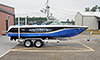
Thanks for the picture Trevor
|
|
 |
|
|
MrMcD
Grand Poobah
Joined: January-28-2014 Location: Folsom, CA Status: Offline Points: 3588 |
Post Options
Thanks(0)
Quote Reply
Posted: July-29-2016 at 4:55pm |
|
Gun Driver and Trevor, thanks for the pictures and shared information.
What I can share if from experience, not from a Marine engineers opinion. Please keep in mind that this was the PCM company's first attempt at fuel injection so maybe they did not have the system worked out quite right? I own one also a 95 GT 40 so I mention this as a participant. The GT 40 Fuel Injection was and is a proven part to be reliable and give very good response so they chose a good system but the fuel feed is not ideal. If this was mine, and mine will probably go out some day also I would change the design. I would eliminate the second fuel inlet at the pump bottom. You don't want hot fuel entering the system. I would take the fuel return line from the Pressure regulator on the Fuel Rail and return that to the fuel tank direct. I hope the tank has a return line built in. You must use Marine Fuel line Approved hose is very expensive but it is not an option to use automotive. A hard line is an option also but boats normally use Marine approved rubber lines in the bottom of the boat. Now fuel is supplied direct to the engine from the tank with less pre heating involved. The second issue is the high pressure pump is mounted very close to the engine block and exhaust manifold where there are heat sources. Normally the high pressure pump is mounted inside the fuel tank so it is always in cool fuel. Maybe add a metal heat shield between the pump and the exhaust. The in line pump like the one from Jegs is normally mounted as close as possible to the fuel tank but mounted on the frame rail. Again cooler than mounted on the engine block next to the exhaust manifold. Your thoughts? I can say the engine does not care where it's fuel comes from as long as a constant source is applied. Remember this is a boat so do any changes safely and well thought out. |
|
|
|
|
MrMcD
Grand Poobah
Joined: January-28-2014 Location: Folsom, CA Status: Offline Points: 3588 |
Post Options
Thanks(0)
Quote Reply
Posted: July-29-2016 at 4:58pm |
|
Another thought, any chance these boats lost an impeller prior to this issue?
If impeller chunks are blocking some of your exhaust coolant on that side it may be exposing your pump to more heat than normal? Just a thought. |
|
|
|
|
gun-driver
Grand Poobah
Joined: July-18-2008 Location: Pittsburgh, Pa Status: Offline Points: 4112 |
Post Options
Thanks(0)
Quote Reply
Posted: July-29-2016 at 10:12pm |
|
Mark, after reading your post I thought maybe I was screwed up and as I thought about it the hot fuel returning made sense. So I did some more investigating I disconnected the cross over line from the return tee plugged the Tee and put the cross over line in a jug and as I thought it pushes fuel out not in.
So my thought of the pump receiving extra fuel for cooling and sending it across to the return is still plausible. My other theory of the pump sending the fuel across to the return when hot instead of priming the rail still has to be tested and I can't do that until Monday because I have to get a special fitting from a hydraulic firm near me to plug the bottom of the pump or the end of the line. As for the inline HPP you posted I may explore that route. I could move the LPP off the motor, mount it on the stringer back towards the tank and then mount the inline HPP on the stringer after that and have a flexible fuel line made using braided line to go up to the fuel rail. Then both pumps will be away from the heat under the motor cover. |
|
|
|
|
MrMcD
Grand Poobah
Joined: January-28-2014 Location: Folsom, CA Status: Offline Points: 3588 |
Post Options
Thanks(0)
Quote Reply
Posted: July-29-2016 at 11:08pm |
|
The design of the low pressure pump gives it plenty of power to pull the fuel from the tank to your engine mount and then to supply the High Pressure Pump. You can move it to the tank area if you wish but I think that risks putting it under water if your bilge fills and that would be bad and could happen any time in a boat.
We need to think more about what PCM thought when they installed the second line in that pump. I can't think of a reason for it to exist? No automotive applications use that system so it must be something they think is important to a marine application. Does it feed the Fuel Rail before or after the pressure regulator? |
|
|
|
|
Gary S
Grand Poobah

Joined: November-30-2006 Location: Illinois Status: Offline Points: 14096 |
Post Options
Thanks(0)
Quote Reply
Posted: July-29-2016 at 11:20pm |
|
I would like to add Mark that it is my understanding from PCM that the low pressure pump was added later. My guess was to help eliminate problems that were happening in the real world maybe a heat soak problem? Does your 95 have the same no FCC system? I had talked to one of their reps at a boat show, he was involved in adding pumps, he remembers how hard it was to do crawling around in the boat

|
|
|
|
|
MrMcD
Grand Poobah
Joined: January-28-2014 Location: Folsom, CA Status: Offline Points: 3588 |
Post Options
Thanks(0)
Quote Reply
Posted: July-30-2016 at 7:25pm |
|
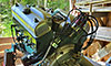
OK, I took my cover off and got pictures of my 95. I also looked at the Fuel system.
I don't like it at all. The return line that should feed to the fuel tank does not. The return line dumps into the second port on the High Pressure Pump. If it could be modified to dump the return into the tank the system would run cooler by far. I could see this design having failure issues. There has to be a valve in the current HPP to receive the return fuel from the pressure regulator and not let pressure from the pump shoot back at the pressure regulator. Silly system. PCM should have got some advice prior to doing this in my opinion. Which is not worth much. If your HPP is bad it would be possible to build a T out of brass couplings that bolt together and use the new Fuel Pump like the one available at JEGS in the pictures and plumb the return line direct into the fuel supply line and then into the High Pressure pump. It would function the same as the factory Nautique system. If it lasts 10 years that would be great and easier than routing a new return line to the tank directly. A couple photo's of mine and the newly installed Timmy T. Thanks for that Tim. Mine is 1' not 3/4 in the 95.     
|
|
|
|
|
gun-driver
Grand Poobah
Joined: July-18-2008 Location: Pittsburgh, Pa Status: Offline Points: 4112 |
Post Options
Thanks(0)
Quote Reply
Posted: July-31-2016 at 12:50am |
|
No
The angled port out of the bottom of the HPP through the stainless line is a return line, extra fuel not used by the HPP crosses over the rear of the motor and into the return line then back to the tank. My guess is that the extra fuel is used to cool the pump then returns to the tank. My theory is that when the HPP overheats it's sending the fuel to the return through that stainless line instead of pressurizing the rail. I have disconnected that line from the return Tee and plugged the tee fitting and the pump port to test this theory but as of today have not the chance to maybe tomorrow. |
|
|
|
|
MrMcD
Grand Poobah
Joined: January-28-2014 Location: Folsom, CA Status: Offline Points: 3588 |
Post Options
Thanks(0)
Quote Reply
Posted: July-31-2016 at 3:41am |
|
Paul, doing it the way you plan will make the fuel pump dead head. Your fuel pressure will jump to the max the pump can attain. Might be 50+.
You have to have a return line. Maybe yours has a second line to the tank. I did not find one on mine. It would be pretty obvious. I think they knew a return was needed and thought what the heck, put it back in the line feeding the HPP. Sounds good until something gets hot. Looking at the fittings used they are good quality but they were purchased from a speed shop type supplier not from an high volume OEM type supplier. They would all be the same color. Gold. The reds and blue fittings are common aftermarket fitting where Bling is needed. |
|
|
|
|
gun-driver
Grand Poobah
Joined: July-18-2008 Location: Pittsburgh, Pa Status: Offline Points: 4112 |
Post Options
Thanks(0)
Quote Reply
Posted: July-31-2016 at 12:46pm |
|
Your not understanding the system set up. There is a return line coming from the starboard
rail (looking from the rear forward) through the pressure regulator back to the tank. (Yours has one too it's right behind the blower hose) you can see the PR right in front of the breakers in your last picture. Follow the line out the bottom of the small silver canister (PR) vacuum hose on top return line on the bottom. If you look at the picture Trevor posted of the parts he removed, the lines on the right are the return to the tank line he cut the rubber line that goes to the tank on an angle The braided line that comes from the bottom of the pump across to the return Tee is what I'm plugging. That line returns "EXTRA" fuel that the pump doesn't use for the rail and returns it to the return line at the Tee. My theory is that when the pump heats up and when the motor is shut off the fuel is returning ( siphoning) from the pump and rail to the tank out the sliver braiided line creating the air lock. |
|
|
|
|
MrMcD
Grand Poobah
Joined: January-28-2014 Location: Folsom, CA Status: Offline Points: 3588 |
Post Options
Thanks(0)
Quote Reply
Posted: July-31-2016 at 1:36pm |
|
I put my head down and looked yesterday and did not see a return fuel hose, only the feed hose was visible. On the driver side I only saw the steering cable. If the return line is there that is good and it should be there.
Maybe some member here can comment on the need for the second line feeding the fuel pump. The new fuels available with a grain mix are much more prone to have fuel vapor lock issues. than petroleum based gasoline. The Fuel rail pressure regulator receives fuel at whatever the pump puts out, could be 47 to 60 PSI, it bleeds off pressure to keep the constant 39 required in this engine. The constant Fuel Pressure lets them predict how much each injector will spray and they tune from that. If fuel pressure drops the injectors won't spray right and if pressure goes up you feed more fuel than planned. The excess fuel bled off goes to the tank and the extra flow keeps the fuel rail cool and helps avoid any hot fuel issues. When I get time I will trace my fuel return line all the way from the rail to its destination. |
|
|
|
|
gun-driver
Grand Poobah
Joined: July-18-2008 Location: Pittsburgh, Pa Status: Offline Points: 4112 |
Post Options
Thanks(0)
Quote Reply
Posted: July-31-2016 at 2:25pm |
|
Pressure regulator works in conjunction with vacuum.
At idle the injectors need less fuel to meet the fuel/air ratio set by the ECA. When the engine is started and at idle fuel pressure will drop from the 39+/- 3 Key on engine off to 31+/-3 as there is more vacuum closing the passage to the rail returning un-needed fuel to the tank. As throttle increases less vacuum causes the fuel pressure to overcome spring pressure, regulator opens allowing more fuel/pressure into the rail. As throttle is increased to WOT fuel pressure overcomes spring pressure even more allowing more fuel to rail pressure increases back up to 39+/- 3 |
|
|
|
|
MrMcD
Grand Poobah
Joined: January-28-2014 Location: Folsom, CA Status: Offline Points: 3588 |
Post Options
Thanks(0)
Quote Reply
Posted: July-31-2016 at 4:47pm |
|
Exactly correct.
Knowing all that why the return line to the pump if yours has a return to the tank. I can't think of any reasonable answer to that question or why PCM thought it was a good idea. You turn the key, Pumps kick on, system pressurizes and its ready to go. I see not reason for the second return. I would block the second return to the pump and see if your start up hot issue goes away. I believe that is your plan and your waiting on fittings. I think it will help with or without a new pump install. |
|
|
|
|
gun-driver
Grand Poobah
Joined: July-18-2008 Location: Pittsburgh, Pa Status: Offline Points: 4112 |
Post Options
Thanks(0)
Quote Reply
Posted: July-31-2016 at 11:32pm |
|
Mark the extra port out of the bottom of the pump "RETURNS" unused fuel from in the HPP to the return line THROUGH the braided line to the return line on the drivers then back to the tank. And yes yours has one.
I did find out today that it is necessary to have that because when I plugged it I ruptured the internal seal and the pump leaked out the top. So my theory of the pump syphoning out that line back to the tank is still to be tested. I have a fitting made up to run the braided return line into the feed line before the LPP that way it should not be able to syphon out due to the anti syphon valve keeping it from back draining to the tank. |
|
|
|
|
MrMcD
Grand Poobah
Joined: January-28-2014 Location: Folsom, CA Status: Offline Points: 3588 |
Post Options
Thanks(0)
Quote Reply
Posted: August-01-2016 at 3:30am |
|
I did a search for regulations on Marine Fuel Lines.
This is interesting and odd but explains what they attempted to do with the pump design on the GT40 system. 15. Fuel pumps on a marine engine must be designed to not leak fuel into the boat. Many are double diaphragm. Today most engines have electric fuel pumps. The pump must be mounted on the engine or within 12 inches of the engine. This minimizes the amount of fuel line that is under pressure. It also means that unlike newer cars the line from the tank to the engine is under negative pressure. In other words, the fuel is sucked to the pump rather than pushed to the pump. That way if there is a leak the engine just starves for fuel and stops. The fuel pump must be fire resistant. 16. Fuel lines from the pump to the carburetor must be metal or USCG Type A marine fuel hose. This hose is fire resistant. The hose from the tank to the pump can be USCG Type A or B. Type B is not fire resistant and is hard to find. 17. Fuel filters can not leak into the boat either and must be fire resistant. 18. Fuel tanks must also be fire resistant and pass a 3 PSI pressure test. Today most fuel tanks on gasoline powered boats are aluminum or plastic (Polyethylene). Both must pass all the requirements of the Coast Guard. Other materials are not prohibited but need to be built to specific standards. The tanks must not be integral with the hull. 19. The fill and vent hose can be USCG type B hose but again it's hard to find. You can use Type A. Also on cars fuel tanks and the whole fuel system are closed and under slight pressure. On boats this is unsafe. If a leak developed anywhere in the system it would literally empty the entire contents of the fuel tank into the bilge of the boat. So boat fuel systems are vented to the atmosphere to keep them at atmospheric pressure. Since January 2011 the rules have changed somewhat due to environmental regulations. Fuel systems are now closed but not allowed to exceed a maximum pressure of 1 psi. This is achieved with a 1 psi pressure relief valve built into the vent line. The system also has a carbon canister to collect and scrub vapors. See Gasoline Fuel Systems http://newboatbuilders.com/pages/fuel.html and Fuel Tanks http://newboatbuilders.com/pages/fuel_tank.html NOTE: GM engines use some of the same parts on both the auto and marine versions. For instance, truck cams are very much the same as cams on boats. However, if it is a fuel injected engine there may be a problem. Most fuel injected auto engines have a pump in the fuel tank that pressurizes the fuel lines. You don't want pressurized lines running through your boat, so you can't have the pump in the tank. On boats the fuel pump is near (within 12 inches) or on the engine and fuel is sucked to the engine rather than pushed. So how do you pressurize the fuel line so the engine will start quickly without having to crank it for several minutes? A time delay on the pump is allowed. By this I mean that on most marine fuel injected engines, when you turn on the ignition the electric pump comes on and pressurizes the short fuel line from the pump to the fuel injection system, it then shuts off until the engine starts, then the pump comes back on. Most marine fuel injected engines do not have a pressurized return line to the tank. They have a built in recirculating tank on the engine, and a gravity feed back to the tank. More Thoughts on Marine Engines |
|
|
|
|
tryathlete
Platinum Member 

Joined: April-19-2013 Location: Lake Villa, IL Status: Offline Points: 1796 |
Post Options
Thanks(0)
Quote Reply
Posted: August-01-2016 at 12:11pm |
|
Ha. This explains why keeping the starter engaged a bit longer when experiencing hot start shutdown would get the engine started.
|
|
|
|
|
TrevorB
Newbie 
Joined: July-01-2016 Location: Wenatchee Wa Status: Offline Points: 14 |
Post Options
Thanks(0)
Quote Reply
Posted: August-02-2016 at 11:31pm |
|
A link to Indmars replacement. I don't see a return on this pump
https://www.bakesonline.com/searchresult.aspx?CategoryID=503&page=3 |
|
|
1995 SNOB GT-40
|
|
|
|
|
tnplicky
Senior Member 

Joined: December-22-2006 Location: C'trl Illinois Status: Offline Points: 333 |
Post Options
Thanks(0)
Quote Reply
Posted: August-08-2016 at 6:46pm |
|
For what it's worth, I took a stab at some power point engineering and drew up a '95 GT-40 fuel system schematic. If there are errors or additions, let me know.

|
|
|
|
|
gun-driver
Grand Poobah
Joined: July-18-2008 Location: Pittsburgh, Pa Status: Offline Points: 4112 |
Post Options
Thanks(0)
Quote Reply
Posted: August-08-2016 at 9:53pm |
|
That's it in a nut shell
|
|
|
|
|
Gary S
Grand Poobah
Joined: November-30-2006 Location: Illinois Status: Offline Points: 14096 |
Post Options
Thanks(0)
Quote Reply
Posted: August-08-2016 at 9:58pm |
|
Enough yacking lets get the old one cut open
|
|
|
|
|
MrMcD
Grand Poobah
Joined: January-28-2014 Location: Folsom, CA Status: Offline Points: 3588 |
Post Options
Thanks(0)
Quote Reply
Posted: August-08-2016 at 10:36pm |
|
Gary, Gun Driver is working on this now. He supplied the picture I post, pictures come from a Master Craft forum if you can believe that.
I think we will know soon how a replacement Carter pump is working for Gun Driver. Looking at this photo I can tell you the OE Pump was made by Carter, it is a geroter and turbine pump. The geroter ( gear pump design ) provides steady high pressure but does not prime well so they add the turbine to help it prime better. The intake side of this pump has two intakes. Geroter pumps are sensitive to pumping any dirt, dirt can lock them up so make sure your feed line has a filter on it, a good filter that is less than 20 micron size. The two bottom pump threaded connections are not pressure ports, they are both intake ports. Any pressure in these lines would be provided by the low pressure supply pump also a Carter design. Every Automotive application I know of uses one feed line and one return line. The second feed line to this High pressure pump comes from the Fuel Rail return line after the pressure regulator. The fuel rail return line also has a line that drains back into the gas tank on these boats so I see no reason for the second return line to the High Pressure pump. Can anyone explain why the second return line would exist? If you want to stay similar to the factory an aftermarket pump could be installed and you could add a T in the feed line, metal or brass and threaded to maintain the factory second feed to the intake. ( aftermarket HPP pumps are $70-$135.00 a little cheaper than the OEM design at $650 that is not available ) The problem with this design is that it returns Hot fuel to the intake feed and fuel injection prefers cool fuel at the intake feed. My only idea on this would be to help have constant supply to the HPP even if the boat is involved in rough water and the tank is splashing around and the feed is not constant. Fuel injection demands a constant flow of fuel to work right. This idea is my WAG!  |
|
|
|
|
MrMcD
Grand Poobah
Joined: January-28-2014 Location: Folsom, CA Status: Offline Points: 3588 |
Post Options
Thanks(0)
Quote Reply
Posted: August-08-2016 at 10:59pm |
Nice design to show the flow on the GT 40 Fuel Injection. I wish I had your power point ability! One update would be for the 2nd hose from the fuel rail to the High Pressure Pump. This hose can work two ways. Fuel can flow from the Fuel Rail Pressure regulator to the High Pressure pump or it can flow fuel from the HPP to the return line. This hose connects to the High Pressure pump intake port. It will have slight pressure from the Low pressure pump. The low pressure pump does not need this by pass it will regulate its flow to meet the demand at 5-7 lbs pressure. Maybe this by pass keeps the low pressure pump running cooler as a safety feature? WAG #2 |
|
|
|
|
Gary S
Grand Poobah
Joined: November-30-2006 Location: Illinois Status: Offline Points: 14096 |
Post Options
Thanks(0)
Quote Reply
Posted: August-08-2016 at 11:28pm |
|
Mark do they or basically any simmiler pump,ie automotive fail is because of bearing failure? I remember at work a truck would get towed in and dropped off. Our mechanic being by himself could not push it in to the bay so he'd take a rubber hammer have one of us turn the key to start it and pound on the bottom of the tank and sure enough they would go. Always seemed that the tanks were just topped up too. Chevys went thru pumps like crazy,Fords went thru oil pans
|
|
|
|
|
gun-driver
Grand Poobah
Joined: July-18-2008 Location: Pittsburgh, Pa Status: Offline Points: 4112 |
Post Options
Thanks(0)
Quote Reply
Posted: August-08-2016 at 11:33pm |
|
I talked to a tech at Carter today getting specs on the stock 962 PFI HPP pump so I could compare it to others on the market. He was not 100% about the extra port as they've been NLA for a while but he believed it was to discharge any vapors to help keep the pump from getting vapor lock.
If you think we have problems you should go to the MC and Malibu sites there's 73 pages of pump problem/discussion on the MC site alone.  |
|
|
|
|
MrMcD
Grand Poobah
Joined: January-28-2014 Location: Folsom, CA Status: Offline Points: 3588 |
Post Options
Thanks(0)
Quote Reply
Posted: August-09-2016 at 12:51am |
Gary the most common issue is dirt and dry starting. The bearings in these are fuel lubricated so any dry start will toast the pump. Engineering says the bearings/bushings will be damaged within 20 seconds on a dry start. Dry starts happen when cars are parked on a side hill, it does not have to be much slope if the car is low on gas. Dirt contamination will damage the pump as it passes through. Any dirt will start wearing on the bushings because it all flows past the moving parts as it is pressurized. I don't mind driving my car all the way to near empty when on the road if I know exactly when I will get gas. If I am heading home I fill up if I am below 1/4 tank to avoid this damage. The third most common issue causing pump failure is bad connections to the battery. The pumps need 12 V plus to operate well. If the ground is bad or the power source is corroded the pump may only see 7 V and it will burn up. Sometimes the pump has 12V when not running but when the load hits it the power source can drop off considerably. If the pump is noisy, it is toast. These are the ones that will respond to a good tap with the rubber hammer normally. This band aid usually only works till you shut it off next time. Damaged bushings make them noisy. Tolerances are pretty tight so damaged parts can start rubbing on other parts making even more noise. They usually fail over time, slowly getting louder till they lock up unless you run them dry when the process goes pretty fast. |
|
|
|
|
gun-driver
Grand Poobah
Joined: July-18-2008 Location: Pittsburgh, Pa Status: Offline Points: 4112 |
Post Options
Thanks(0)
Quote Reply
Posted: August-09-2016 at 2:05am |
|
Once again NO!!!
Below is a post from the MC site where they were under the same assumption. The post is the same information I was told and saw when I disconnected the braided hose from the return line to the tank and turned on the pumps. The drawing is correct!!! Took the pump off my 1998 Maristar and talked to a tech at my local mastercraft dealer. There is one inlet and two outlets to these pumps. It appears at first glance that there are two inlets but the angled port (at the bottom) returns air/bubbles in the line to the tank.There is a check valve in this port to keep the pump from drawing air during operation. |
|
|
|
|
MrMcD
Grand Poobah
Joined: January-28-2014 Location: Folsom, CA Status: Offline Points: 3588 |
Post Options
Thanks(0)
Quote Reply
Posted: August-09-2016 at 5:40am |
|
Gun Driver, so far I have not seen a air separating check valve. Not in fuel or even brake ABS systems. If there was such a valve it would be really popular. You could eliminate bleeding brakes.
The pressure releaf valve on the fuel rail can bleed off a lot of fuel. At times that bleed off may be at 20 psi. Headed back to the tank.. I still scratch my head why this second line exists. I think we can figure it out. |
|
|
|
|
gun-driver
Grand Poobah
Joined: July-18-2008 Location: Pittsburgh, Pa Status: Offline Points: 4112 |
Post Options
Thanks(0)
Quote Reply
Posted: August-09-2016 at 12:47pm |
|
Maybe it was one of those "good idea bad plan" and never really worked right from the get go hence the reason they are NLA.
|
|
|
|
|
tryathlete
Platinum Member
Joined: April-19-2013 Location: Lake Villa, IL Status: Offline Points: 1796 |
Post Options
Thanks(0)
Quote Reply
Posted: August-09-2016 at 1:14pm |
|
I am of the thinking that when one replaces the fuel filter and does not fully fill the container with fuel and bleed the air that is trapped--there may be a possibility that LPP's are not failed but are being replaced needlessly.
I'm saying this because when I had a Nautiqie dealer replace my fuel filter, that's when all my troubles with starting erupted. I must have bled the schrader a dozen times before deciding to replace the LPP due to start and die issues I attributed to the LPP. Perhaps if I'd simply removed the FCT housing and filled it with fuel, or kept bleeding the trapped air from the valve, I'd have not needed a new LPP at only 500 hours of engine time. |
|
|
|
|
Gary S
Grand Poobah
Joined: November-30-2006 Location: Illinois Status: Offline Points: 14096 |
Post Options
Thanks(0)
Quote Reply
Posted: August-09-2016 at 1:15pm |
|
I don't know about the bad plan part, I saw in some of those threads that just about a year ago or so that rock auto was closing out those pumps for around 20 bucks. 60 bucks and you'd be set for life. What I'm not happy with is the planned obsolescence, PCM has no support of these complex proprietary systems. Someday we will just have to trade in every year or two like those on PN
|
|
|
|
|
Post Reply
|
Page <1234 5> |
 Tweet
Tweet
|
| Forum Jump | Forum Permissions You cannot post new topics in this forum You cannot reply to topics in this forum You cannot delete your posts in this forum You cannot edit your posts in this forum You cannot create polls in this forum You cannot vote in polls in this forum |


 Topic Options
 tnplicky wrote: