 Boats For Sale:


Flow of raw water through motor |
Post Reply 
|
Page 123> |
| Author | ||
t.franscioni 
Groupie 
Joined: February-13-2015 Location: Salinas, CA Status: Offline Points: 68 |
 Post Options Post Options
") Thanks(0) Thanks(0)
 Quote Reply Quote Reply
 Topic: Flow of raw water through motor Topic: Flow of raw water through motorPosted: April-28-2016 at 2:58am |
|
|
Been rebuilding and restoring my GT40 and trying to figure out the flow of water through the motor before it goes back into boat. Im sure this is wrong but I will start with this flow pattern and you guys correct me. Water comes into the upper thermostat housing (via raw water pump), upon startup thermostat is closed so water can't pass down into the 1.25" white stripe rubber pcm hose that feeds the engine water pump so until warmed up it gets directed from the upper thermostat housing intake straight to the 2 upper thermostat housing outputs which direct the flow of water to the right and left exhaust manifolds and then is expelled overboard. When engine reaches temp the thermostat opens allowing raw water down into the 1.25" white stripe pcm hose that feeds the engine water pump which then pushes water into the right and left side of the block where it flows up each side and exits out the lower intake plenum into the upper thermostat housing and out to the right and left exhaust manifolds and expelled overboard. Im sure that's wrong because with that flow pattern I don't have any water running to the engine water pump and through the block UNTIL the thermostat opens....enlighten me please...

|
||
 |
||
|
Duane in Indy
Platinum Member 
Joined: October-26-2015 Location: Indiana Status: Offline Points: 1578 |
Post Options
Thanks(1)
Quote Reply
Posted: April-28-2016 at 6:31am |
|
 This diagram "may" help. Thermostats deadhead water leaving the block which allows water inside the block to heat up to the point the the thermostat opens and allows flow out of the intake. The engine water pump should have water to it 100% of the time. There are bypass holes inside the thermo housing that allows water to route to the exhaust until it is overcome by heated water exiting the engine. All systems vary somewhat. I may stand corrected but this is my take. Hope others can help |
||
|
Keep it as original as YOU want it
1978 Mustang (modified) |
||
|
||
|
DayTony
Gold Member

Joined: June-30-2013 Location: Salem MA Status: Offline Points: 830 |
Post Options
Thanks(0)
Quote Reply
Posted: April-28-2016 at 6:43am |
|
|
I'm not familiar with the gt40 particularly. so exact application might differ. But most raw water cooled engines are similar in design.
your forgetting about your circulating pump which is the main center pulley on the front of the engine. Most engines the coolant flows from the block into the heads. unless its a cadillac northstar then it goes all over the place and never gets a chance to normalize. but thats another story. Anyways i found this picture in a google search 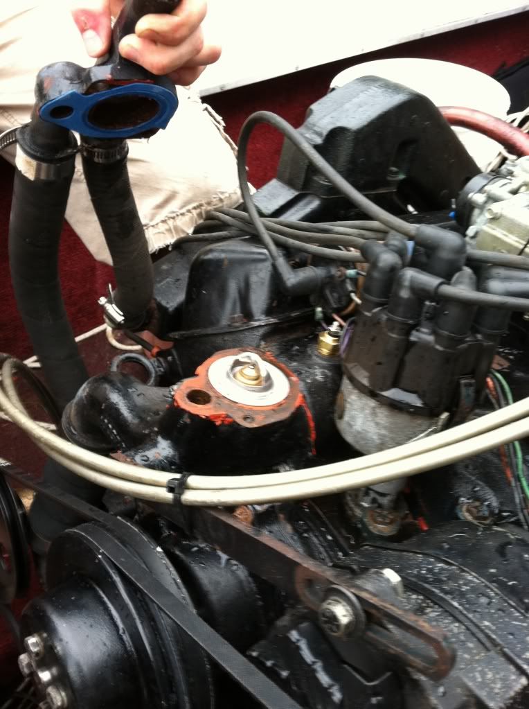 That smaller hole supplies water to the circulating pump on demand. meaning the RWP is supplying the water to the circ pump and anything the circ pump doesn't want will flow through and out the tstat housing. once the engine warms the water thats before the tstat enough to open it the circ pump pretty much takes the majority of that feed and circulates it rather than it going through the bypass. |
||
|
1988 Barefoot nautique-454
|
||
|
||
|
GottaSki
Grand Poobah 
Joined: April-21-2005 Location: NE CT Status: Offline Points: 3327 |
Post Options
Thanks(0)
Quote Reply
Posted: April-28-2016 at 11:12am |
|
|
Tom you have it quite wrong, not certain where to begin.
Tony and Duane got it down. Fresh water can always get to the engine. and stays in the circ loop. Any extra goes to the manifolds. Your manifolds stay somewhat dry till the engine fills, if it was drained prior. The Thermostat opens, letting too-hot water out of the circ loop, to be replaced my fresh water. |
||
|
"There is nothing, absolutely nothing, half so much worthwhile as messing around with boats...simply messing."
River Rat to Mole |
||
|
||
|
t.franscioni
Groupie
Joined: February-13-2015 Location: Salinas, CA Status: Offline Points: 68 |
Post Options
Thanks(0)
Quote Reply
Posted: April-28-2016 at 12:22pm |
|
|
That makes sense. Behind the engine water there are two water jackets. Looks like one going to left side of block and one to right side. Are this both pump discharge jackets or is one a discharge and one an intake for the engine water pump? So the closed loop (prior to thermostat opening) is circulated between those two jackets behind engine water pump? Or are those both discharge jackets that allows water to the right and left side of block and the closed loop (prior to thermostat opening) is completed in the upper thermostat housing?
|
||
|
||
|
8122pbrainard
Grand Poobah

Joined: September-14-2006 Location: Three Lakes Wi. Status: Offline Points: 41040 |
Post Options
Thanks(0)
Quote Reply
Posted: April-28-2016 at 12:27pm |
|
|
Thomas,
Behind the circ pump there are two ports to both sides of the block. Circulation to both sides of the block is only when the T stat opens. |
||
|
||
|
t.franscioni
Groupie
Joined: February-13-2015 Location: Salinas, CA Status: Offline Points: 68 |
Post Options
Thanks(0)
Quote Reply
Posted: April-28-2016 at 12:41pm |
|
|
Here is a picture with the engine water pump off. The top hole in the lower intake plenum is discharge from engine block and heads? The two right and left holes where the engine circulation water pump goes are both circ pump discharge or is one intake and one discharge? I'm talking about just when the system in is "closed loop" for lack of better term I'm referring to before the thermostat opens. I'm getting it slowly here.... Thanks
|
||
|
||
|
8122pbrainard
Grand Poobah
Joined: September-14-2006 Location: Three Lakes Wi. Status: Offline Points: 41040 |
Post Options
Thanks(0)
Quote Reply
Posted: April-28-2016 at 12:54pm |
|
|
Thomas,
The top hole is common to both sides of the block. The two behind the circ pump go to the left and right sides of the block and feed the pump. Water from the RWP is constantly being pumped out the exhaust manifolds and only diverted to the engine when the T stat opens. |
||
|
||
|
TRBenj
Grand Poobah

Joined: June-29-2005 Location: NWCT Status: Offline Points: 21107 |
Post Options
Thanks(0)
Quote Reply
Posted: April-28-2016 at 1:17pm |
|
|
I think pretty much that entire statement is incorrect, Pete.
|
||
|
||
|
t.franscioni
Groupie
Joined: February-13-2015 Location: Salinas, CA Status: Offline Points: 68 |
Post Options
Thanks(0)
Quote Reply
Posted: April-28-2016 at 1:46pm |
|
|
Ok so maybe I'm more screwed up that I figured....Both right and left holes behind circ pump are INTAKES for the circ pump? Which means the top hole on the intake plenum is where the water flows into the engine? So if those 2 holes behind circ pump are intakes then circ pump is pumping water INTO the 1.25" pcm white strip hose that goes up to the thermostat housing?
|
||
|
||
|
8122pbrainard
Grand Poobah
Joined: September-14-2006 Location: Three Lakes Wi. Status: Offline Points: 41040 |
Post Options
Thanks(0)
Quote Reply
Posted: April-28-2016 at 1:50pm |
|
Tim, How so? |
||
|
||
|
Gary S
Grand Poobah

Joined: November-30-2006 Location: Illinois Status: Offline Points: 14096 |
Post Options
Thanks(0)
Quote Reply
Posted: April-28-2016 at 1:55pm |
|
|
No they both are the intakes of the block,the water comes into the circulation pump thru the round hose, then thru those holes in the block circulates thru each cylinder bank then into the heads. Then out thru the heads into the intake manifold then out thru the thermostat mounting
|
||
|
||
|
TRBenj
Grand Poobah
Joined: June-29-2005 Location: NWCT Status: Offline Points: 21107 |
Post Options
Thanks(0)
Quote Reply
Posted: April-28-2016 at 2:14pm |
|
|
Like Gary said, the large (1.75") hose feeding the circ pump from the stat housing is the inlet. That passage is always open regardless of thermostat position- like was said above, the block will always fill up with water if it's empty. The 2 ports on the back side of the pump are the outlets (of the pump, ie, inlet to the block). The engine fills/flows from the bottom up (block-->heads-->intake) and the thermostat controls water flow out of the intake. Even when the block is filling, there will be some amount of water cooling the exh manifolds.
This is the basic PCM ford set up. Other cooling systems do it a little differently- Chryslers, HM's and interceptors that lacked circ pumps, LT1 indmars (reverse cooled), fresh water cooled engines, etc. |
||
|
||
|
DrCC
Grand Poobah

Joined: April-12-2004 Location: at home Status: Offline Points: 2867 |
Post Options
Thanks(0)
Quote Reply
Posted: April-28-2016 at 2:15pm |
|
|
Actually the therm hole is both an "In" and a "Out"
So, the therm housing is kind of like the "brain" or the "Dictator" |
||
|
||
|
8122pbrainard
Grand Poobah
Joined: September-14-2006 Location: Three Lakes Wi. Status: Offline Points: 41040 |
Post Options
Thanks(0)
Quote Reply
Posted: April-28-2016 at 2:31pm |
|
So what's incorrect with pretty much of my entire statement?? Tim, just so I don't confuse you any more with my wording, I found a very nice PICTURE on how it works.  Note the picture does show water exiting via the risers and not the manifolds and then out the risers. |
||
|
||
|
DrCC
Grand Poobah
Joined: April-12-2004 Location: at home Status: Offline Points: 2867 |
Post Options
Thanks(0)
Quote Reply
Posted: April-28-2016 at 2:39pm |
|
|
But the animation is wrong. We do have a bypass that feeds the exhaust before the tstat opens.
|
||
|
||
|
GMacLaren
Senior Member 

Joined: August-22-2013 Location: St. Louis, MO Status: Offline Points: 495 |
Post Options
Thanks(0)
Quote Reply
Posted: April-28-2016 at 5:19pm |
|
|
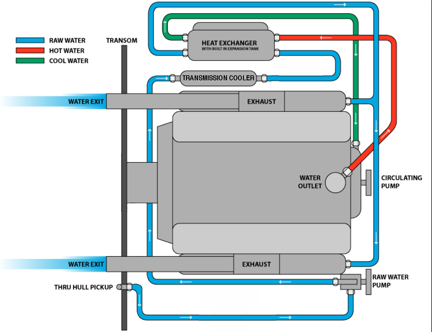
FWIW -- This is the way the water flows through MacSkier:
MacSkier cooling You will have to follow the links to see how this was determined. I'm now quite confident of my understanding of the cooling system on the 1972 Skier. (The thermostat may never open.) -=Grant=- |
||
|
||
|
GMacLaren
Senior Member
Joined: August-22-2013 Location: St. Louis, MO Status: Offline Points: 495 |
Post Options
Thanks(0)
Quote Reply
Posted: April-28-2016 at 5:26pm |
|
Not true for my boat. |
||
|
||
|
GMacLaren
Senior Member
Joined: August-22-2013 Location: St. Louis, MO Status: Offline Points: 495 |
Post Options
Thanks(0)
Quote Reply
Posted: April-29-2016 at 11:49am |
|
|
My boat’s cooling system uses lake water to cool the engine — a 302 Ford V-8, marinized as a Conquerer-Crusader (when they were owned by Thermo Electron, equipped with its original (1972) exhaust manifolds.
Unlike the closed loop systems systems found in cars and many boats (which use a "radiator" or heat exchanger and thermostat to supply coolant of an appropriate temperature), the cooling system described here uses the practically unlimited amount of lake water to cool the engine. A "raw water pump" moves a large volume of lake water into the boat, through the power plant and -- mixed with the engine's exhaust, out of the boat. When the water exits the RWP, it first passes through a small heat exchanger used to cool the transmissions cooler. (This increases the water's temperature a few degrees. We measured it.) Leaving the transmission cooler, the water enters a two-part chamber containing 1) a pressure relief valve and 2) a thermostat. The two chambers are adjacent, but not completely separated. There is a passageway between them. The lake water is pumped into the chamber containing the pressure relief valve. The valve is pushed open, and much of the water flows through it, then out the top of the chamber and on to the front of the exhaust manifold — cooling the manifold. The water that does not exit the chamber via this route, enters the chamber containing the (now closed, and possibly always closed) thermostat, then out of that chamber to the engine’s circulating pump — a recirculating type pump. The pump pushes this water through the engine block, through its heads and through its intake manifold. The water exits the exhaust manifold (where a car’s thermostat would be located.) The engine’s pump pumps the water into the front of exhaust manifold — and aft, via two “side” passageways in the manifold. A cross section of the exhaust manifold reveals four passages; one for the exhaust gases, and three for water. The top passage carries the water previously described, i.e., via the pressure relief valve (and via the thermostat if open.) The two other passages, one on each side of the manifold are fed by one inlet at the manifold’s front. At the rear (aft end) of the manifold, there are three possible exits, 1) a side exit to mix with the exhaust gases, 2) another side exit to mix with the exhaust gases, and 3) a bottom exit that carries water back to the thermostat chamber. I refer to this “bottom” flow of water as the “lower loop.” It is this “lower loop” water that has been heated by the engine block, heads, intake manifold and exhaust manifold. It is circulated by the engine’s pump back to the thermostat chamber where it is mixed with lake water being introduced by the RWP. If there is enough of this “lower loop” heated water returned to the thermostat housing it will raise the water temperature in the housing enough to open the thermostat, permitting more cool lake water to enter the block, etc. If there not enough of this “lower loop” water to open the ‘stat, the ’stat will stay closed. We have experimented enough with this system to know that restricting “lower loop” water from exiting the rear of manifold, we can raise operating temperatures to desirable ranges. But we will not be doing that until we can experience higher lake water temperatures. In summary, if you want good, predictable engine operating temperatures in your inboard boat, get one with a “closed loop” system. -=Grant=- |
||
|
||
|
TRBenj
Grand Poobah
Joined: June-29-2005 Location: NWCT Status: Offline Points: 21107 |
Post Options
Thanks(1)
Quote Reply
Posted: April-29-2016 at 12:43pm |
|
|
Grant, you have a Conquerer-crusader (when they were owned by Thermo Electron). Not sure where you got PWC.
|
||
|
||
|
DrCC
Grand Poobah
Joined: April-12-2004 Location: at home Status: Offline Points: 2867 |
Post Options
Thanks(0)
Quote Reply
Posted: April-29-2016 at 2:00pm |
|
|
He probably just got the M upsidedown, then the C exchanged places when he wasn't looking.
|
||
|
||
|
8122pbrainard
Grand Poobah
Joined: September-14-2006 Location: Three Lakes Wi. Status: Offline Points: 41040 |
Post Options
Thanks(0)
Quote Reply
Posted: April-29-2016 at 3:59pm |
|
Plus Grant, you're confusing Thomas the OP who has a PCM!! Nice schematic you drew of you Conquerer-Crusader's cooling system but again, you're confusing poor Thomas!!! 
|
||
|
||
|
t.franscioni
Groupie
Joined: February-13-2015 Location: Salinas, CA Status: Offline Points: 68 |
Post Options
Thanks(0)
Quote Reply
Posted: April-29-2016 at 4:14pm |
|
|
Im so confused.... I'm not even sure who I am anymore?
|
||
|
||
|
t.franscioni
Groupie
Joined: February-13-2015 Location: Salinas, CA Status: Offline Points: 68 |
Post Options
Thanks(0)
Quote Reply
Posted: April-29-2016 at 4:17pm |
|
|
Iv settled on the fact that as long as I put the motor back together with the cooling components in there correct places the motor will figure out the correct way to flow the cooling water through itself.
|
||
|
||
|
Gary S
Grand Poobah
Joined: November-30-2006 Location: Illinois Status: Offline Points: 14096 |
Post Options
Thanks(0)
Quote Reply
Posted: April-29-2016 at 4:50pm |
|
|
Exactly Thomas. Much like sausage you don't want to know how it's made. Just remember - never run it dry and keep the clamps tight.
|
||
|
||
|
8122pbrainard
Grand Poobah
Joined: September-14-2006 Location: Three Lakes Wi. Status: Offline Points: 41040 |
Post Options
Thanks(0)
Quote Reply
Posted: April-29-2016 at 5:00pm |
|
Thomas, Just don't look at Grant's schematic!!  Just as you mentioned, put it back together and start it up!! Just as you mentioned, put it back together and start it up!! 
|
||
|
||
|
C-Bass
Platinum Member

Joined: November-18-2008 Location: Columbus, IN Status: Offline Points: 1248 |
Post Options
Thanks(0)
Quote Reply
Posted: April-29-2016 at 5:34pm |
|
Gary, are you talking about his sausage or his cooling system? |
||
|
||
|
GMacLaren
Senior Member
Joined: August-22-2013 Location: St. Louis, MO Status: Offline Points: 495 |
Post Options
Thanks(0)
Quote Reply
Posted: April-29-2016 at 5:50pm |
|
Errrr . . . Can you spell Dyslexia? |
||
|
||
|
Gary S
Grand Poobah
Joined: November-30-2006 Location: Illinois Status: Offline Points: 14096 |
Post Options
Thanks(0)
Quote Reply
Posted: April-29-2016 at 6:33pm |
|
Yes both
|
||
|
||
|
GMacLaren
Senior Member
Joined: August-22-2013 Location: St. Louis, MO Status: Offline Points: 495 |
Post Options
Thanks(0)
Quote Reply
Posted: April-29-2016 at 6:45pm |
|
|
A better way:
 |
||
|
||
|
Post Reply
|
Page 123> |
 Tweet
Tweet
|
| Forum Jump | Forum Permissions You cannot post new topics in this forum You cannot reply to topics in this forum You cannot delete your posts in this forum You cannot edit your posts in this forum You cannot create polls in this forum You cannot vote in polls in this forum |


 Topic Options
 TRBenj wrote: